|
|
PB-250 |
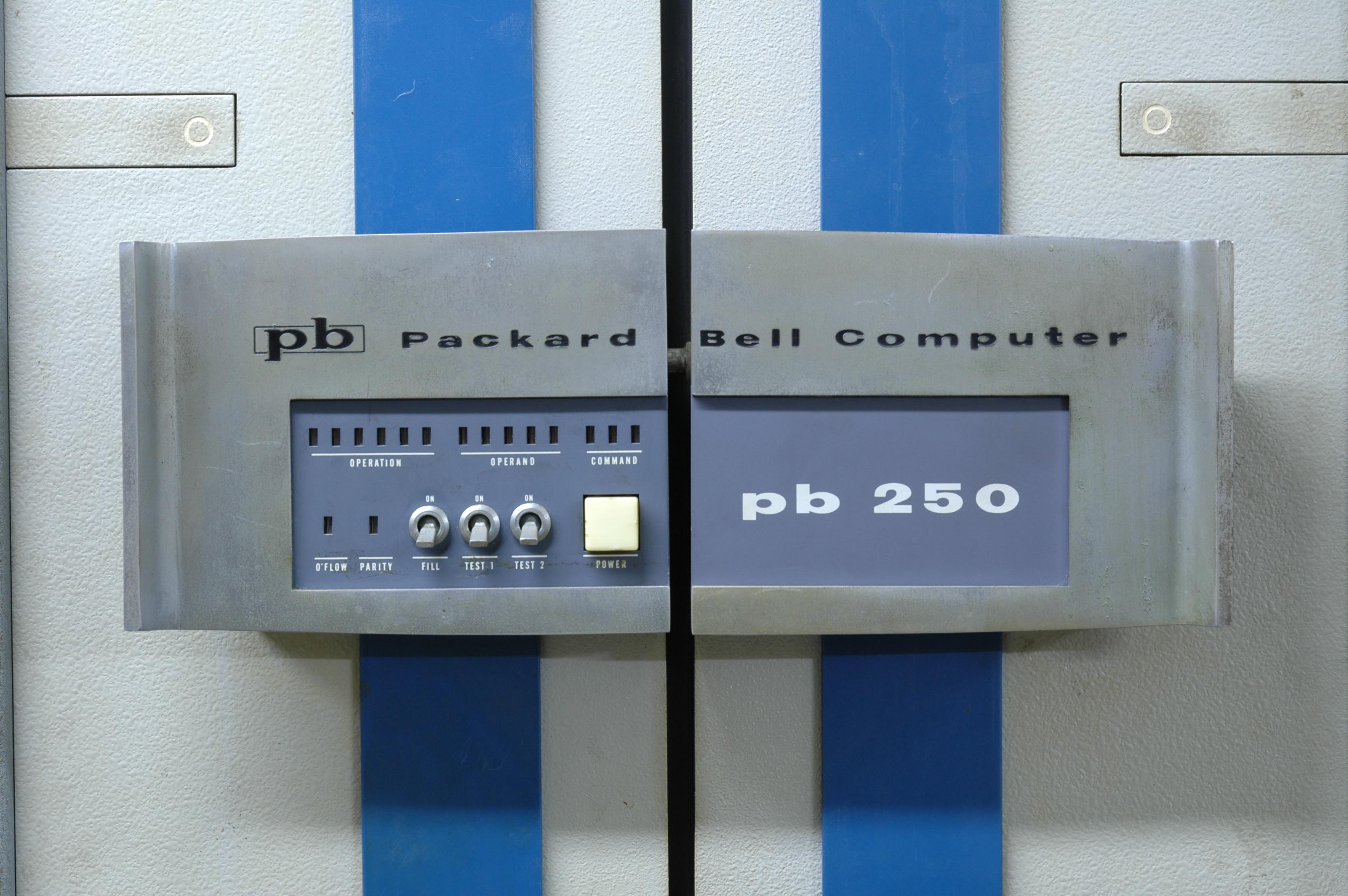
| Who | Packard Bell Computer |
| What | PB 250 |
| When | 1961 |
| Why | General-purpose minicomputer |
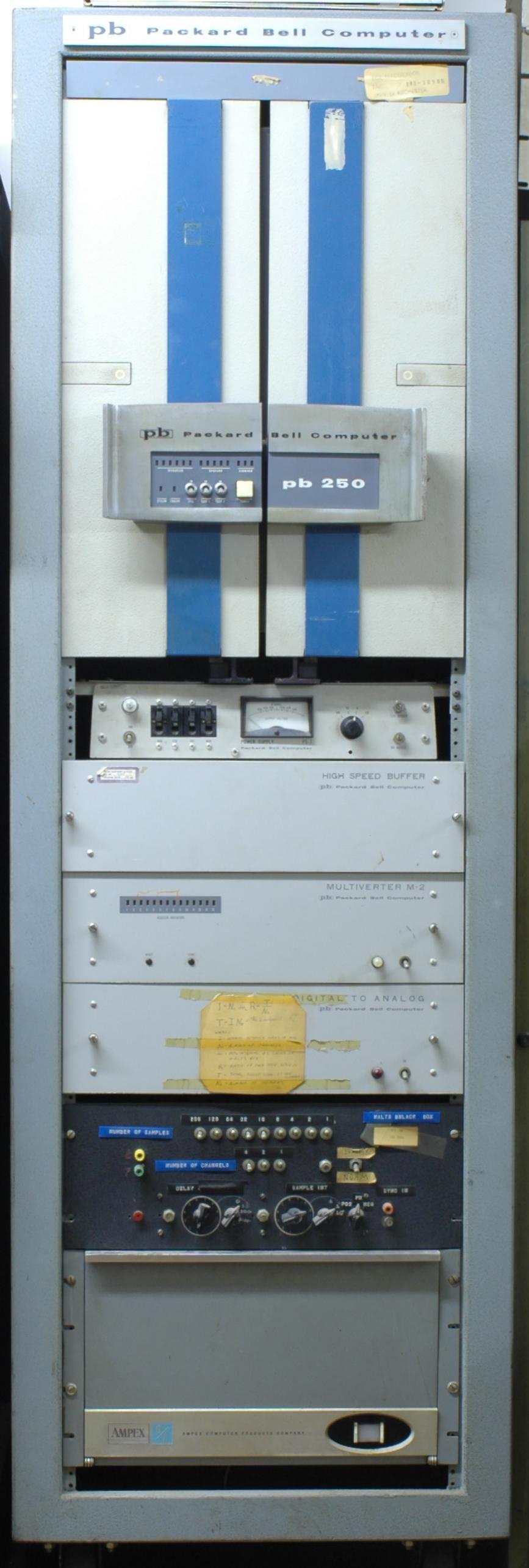
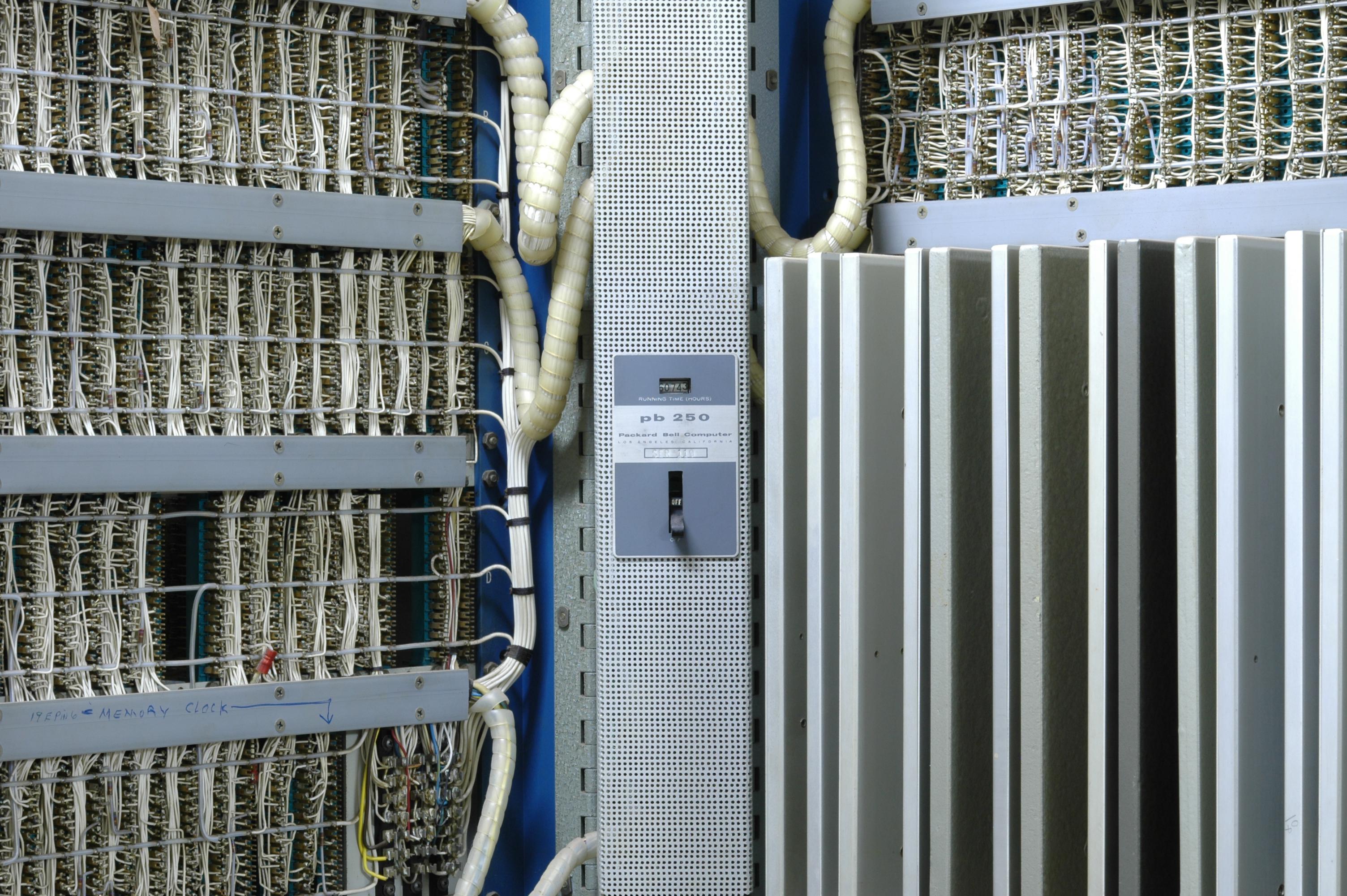
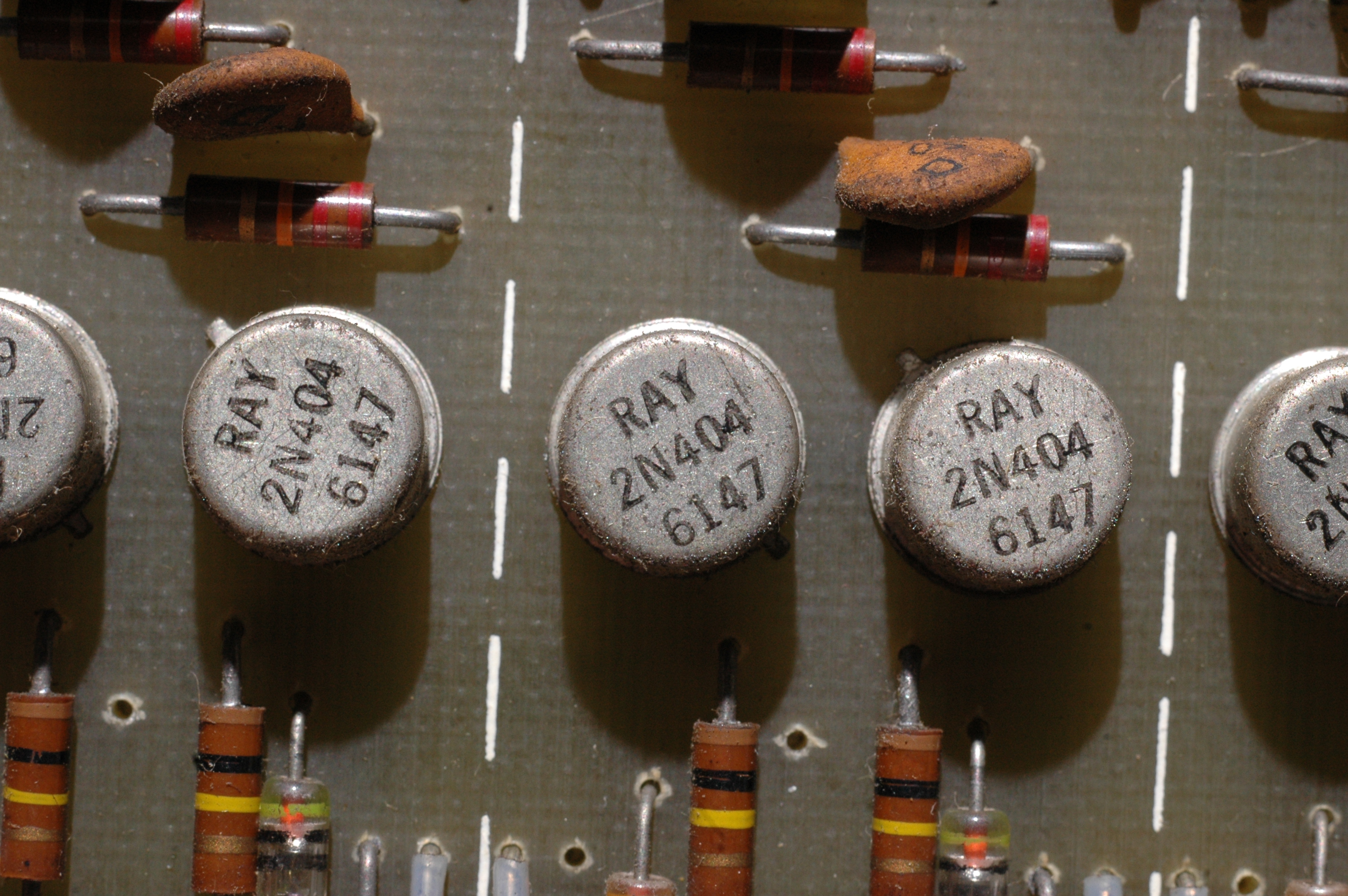
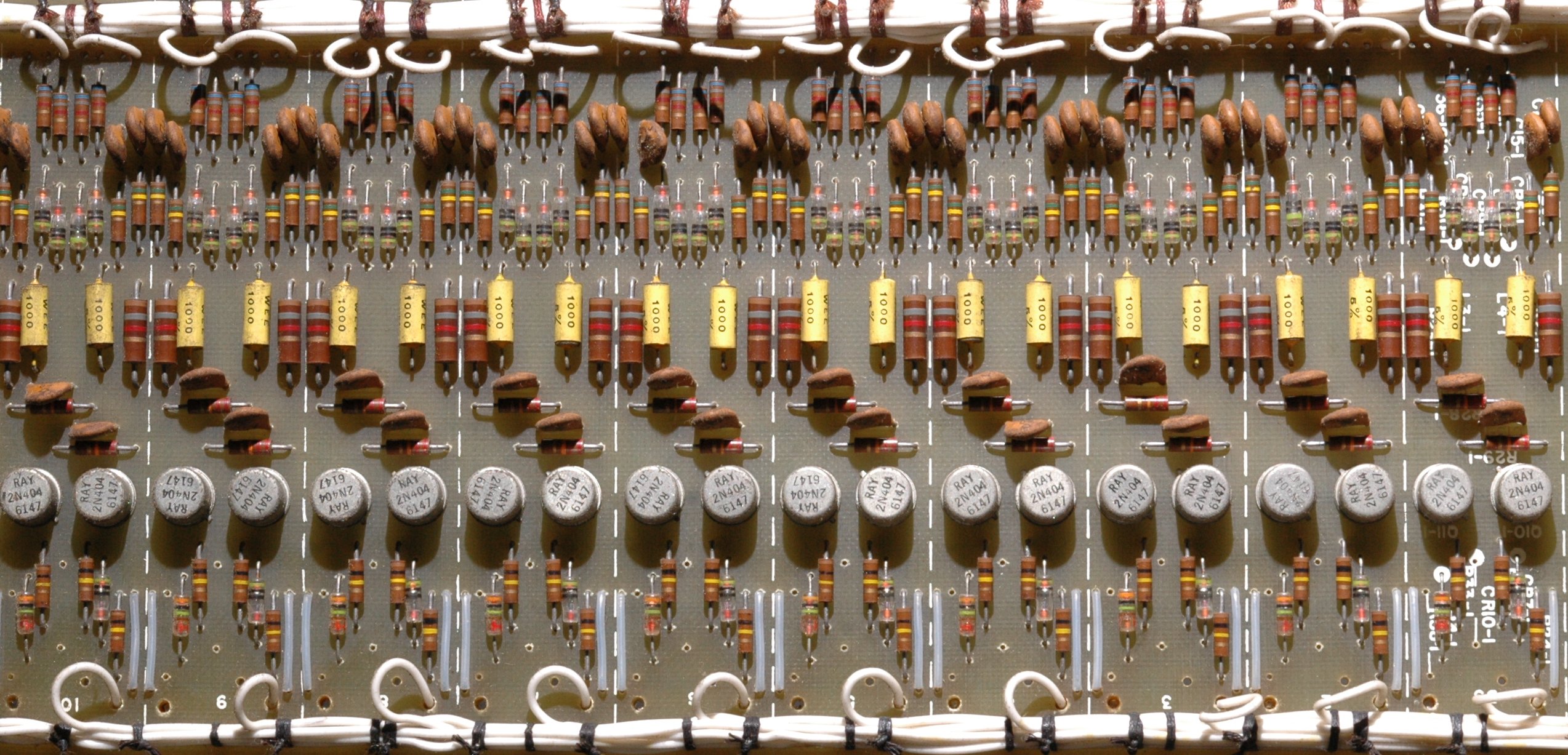
The PB-250 is a 22-bit minicomputer from 1961. It is constructed of discrete transistors, diodes and resistors, and uses delay lines for main memory. This particular system was used in a laboratory for controlling scientific experiments.
We have scanned several manuals for the PB-250:
Programming Manual
SNAP I Assembler
Technical Manual Vol 1
Technical Manual Vol 2
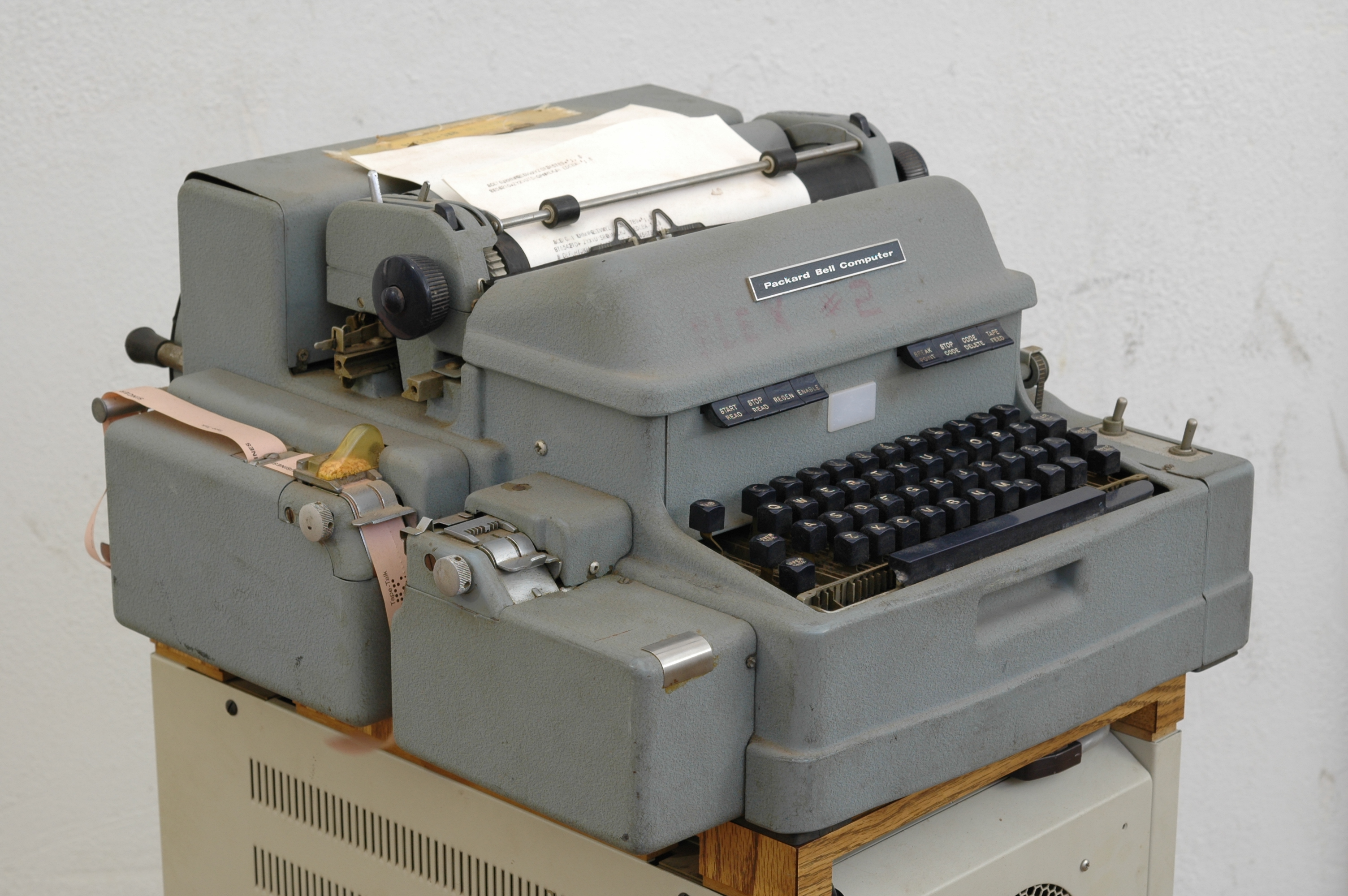
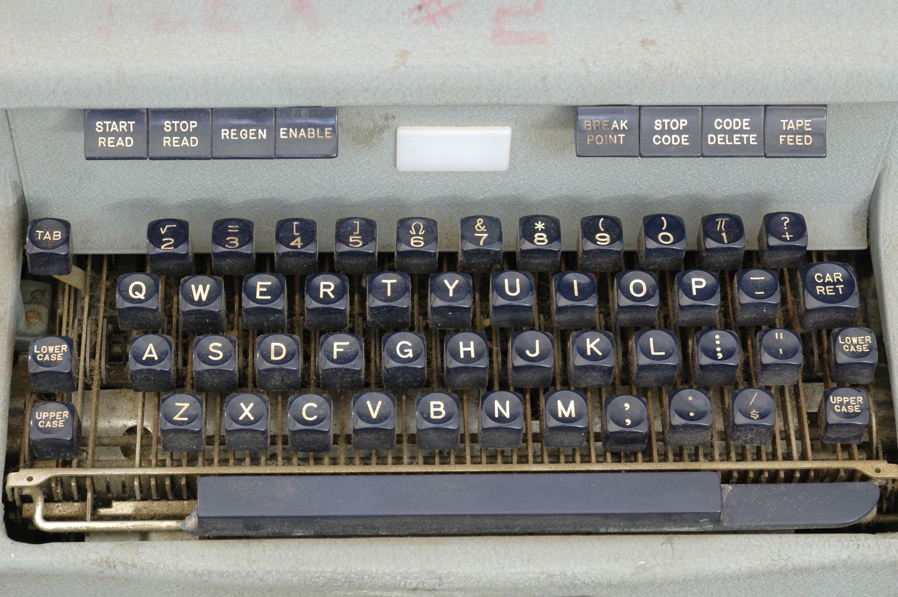
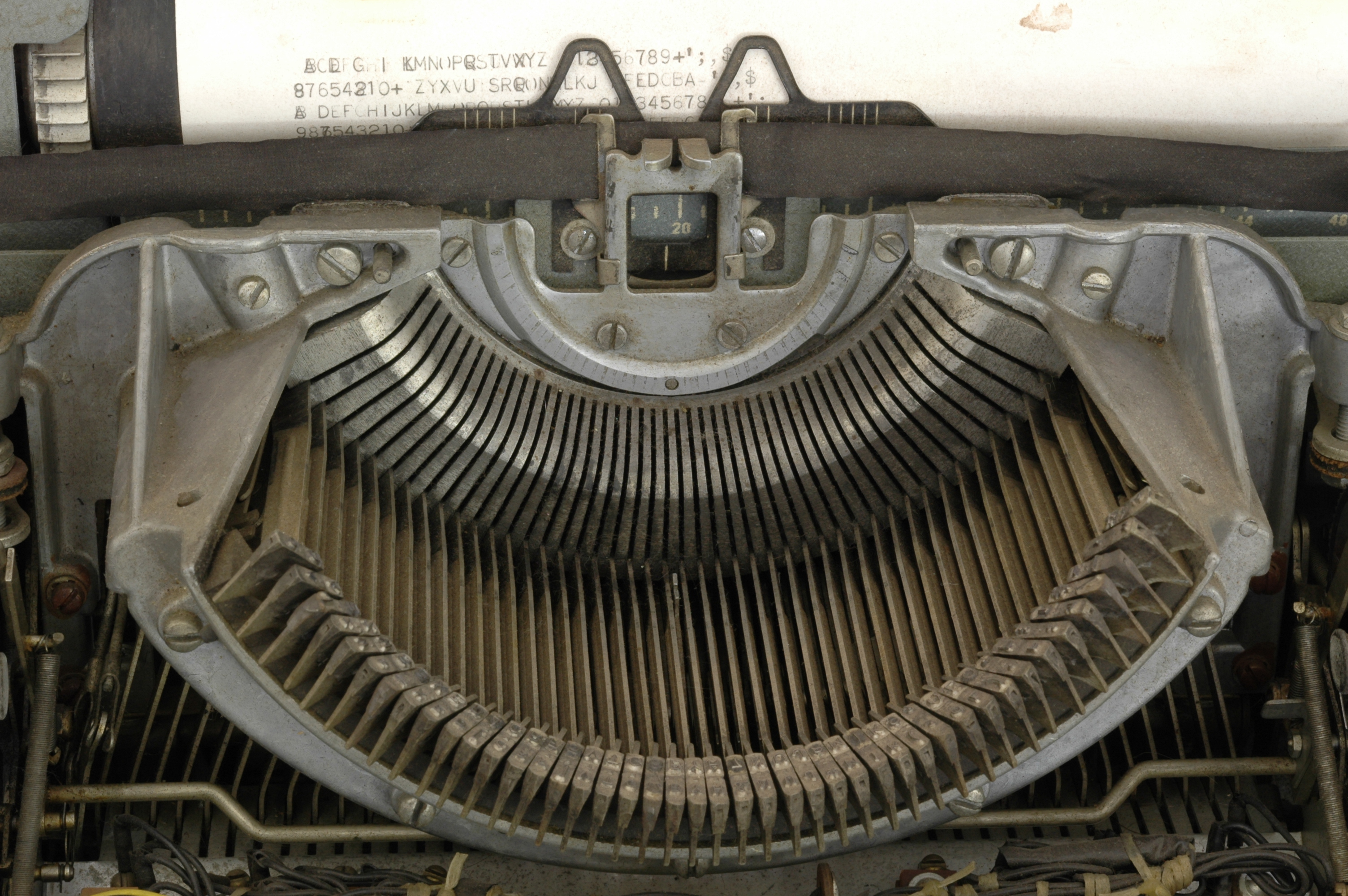
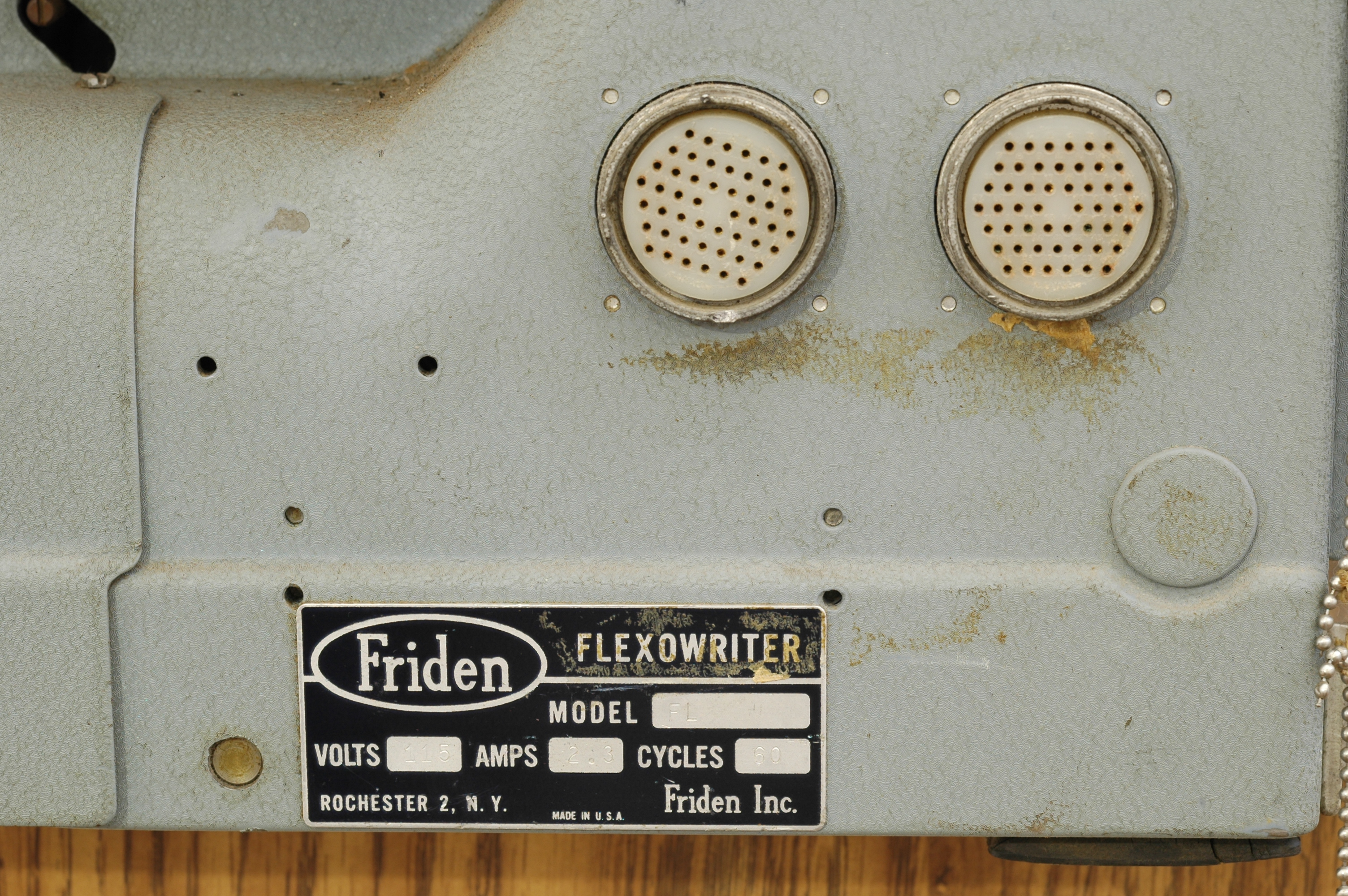
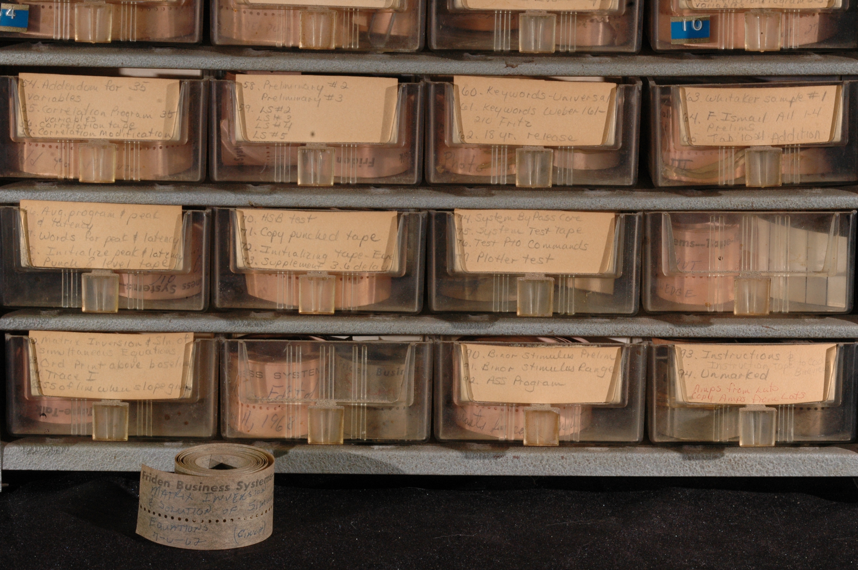
The PB-250 uses a Friden Flexowriter for the console. Programs are stored on paper tape and read in via the flexowriter when they need to be assembled and executed.
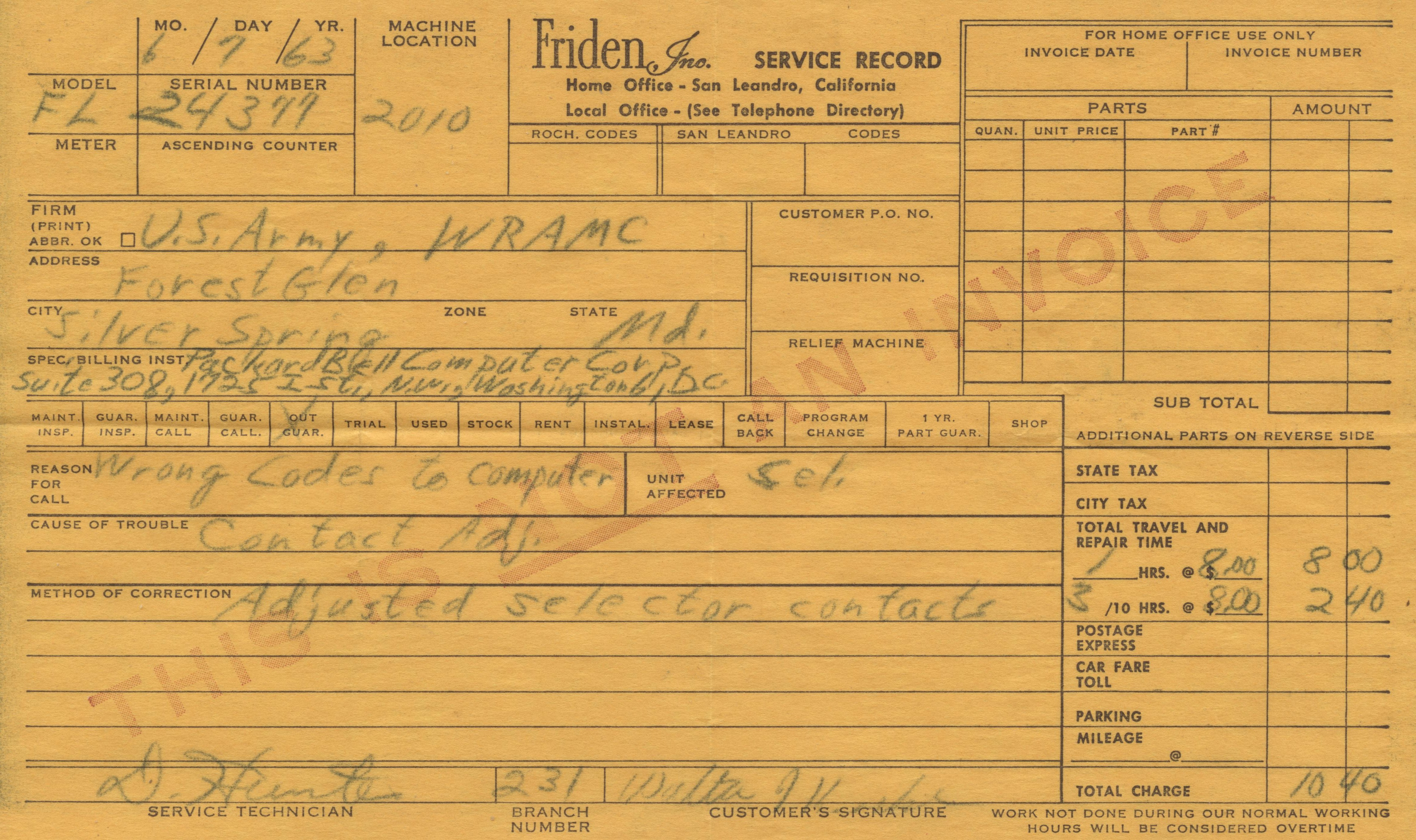
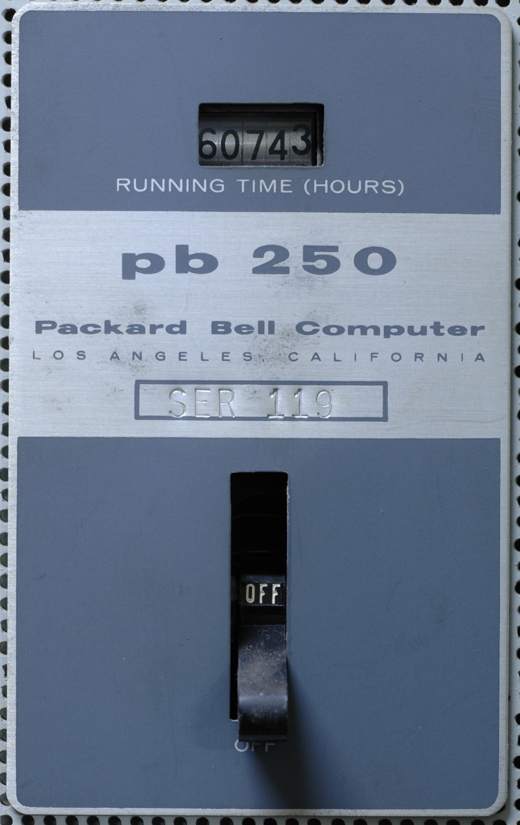
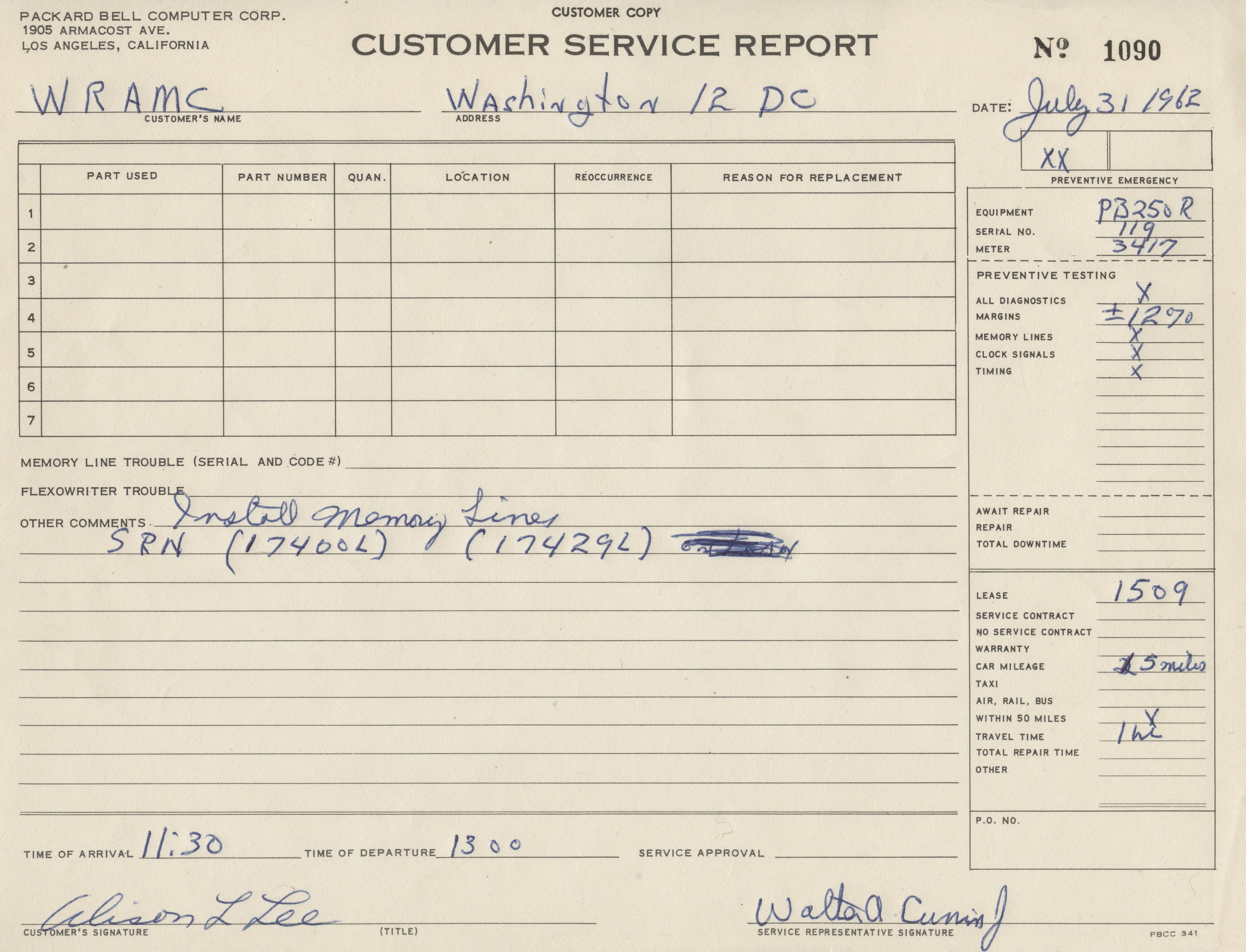
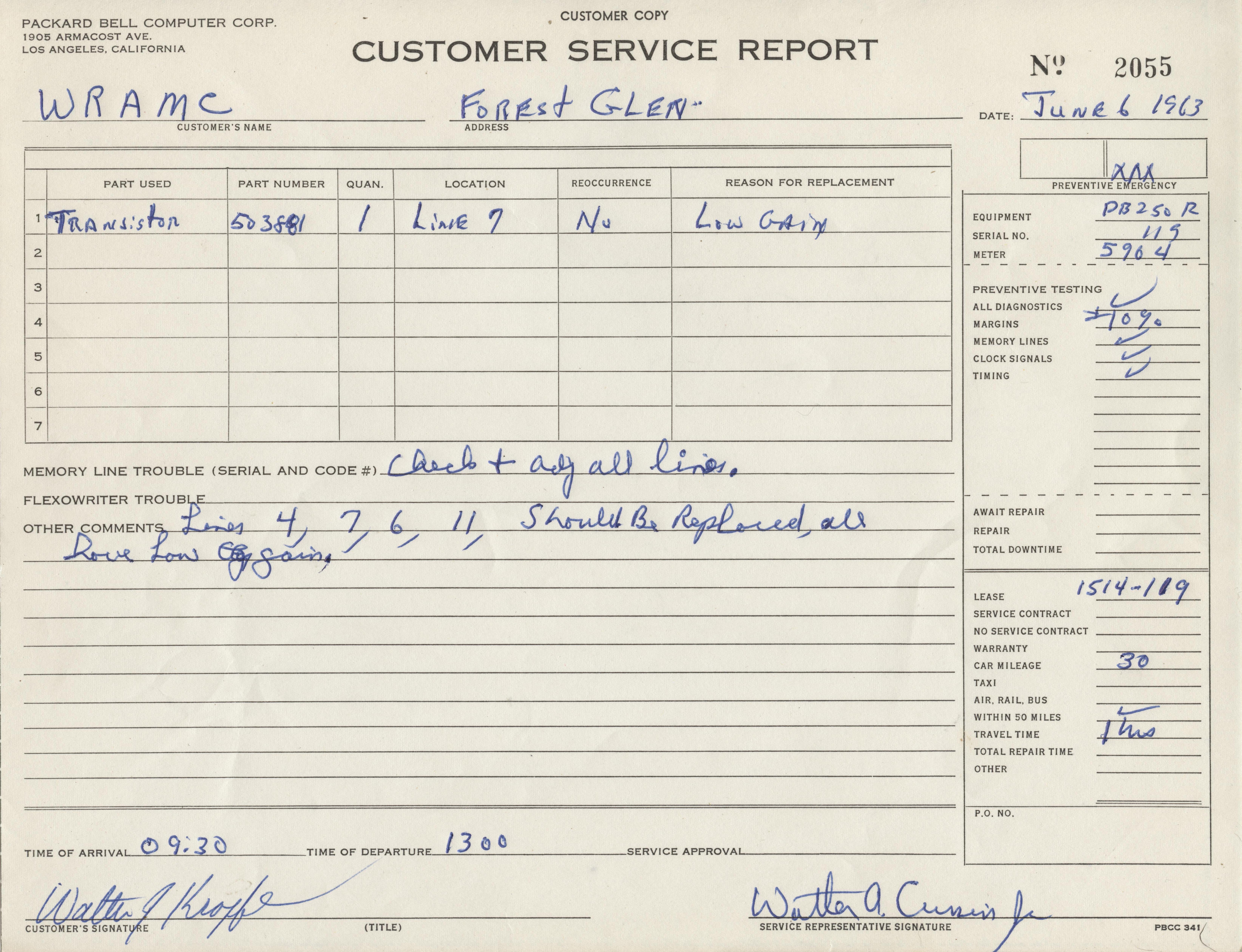
This particular PB-250 was originally in use at Walter Reed Medical Center. From the power supply meter readings logged by field service, it looks like the system was in use a little over 40 hours a week in the early 60s. It was later in use at the University of Rochester Center for Visual Science.
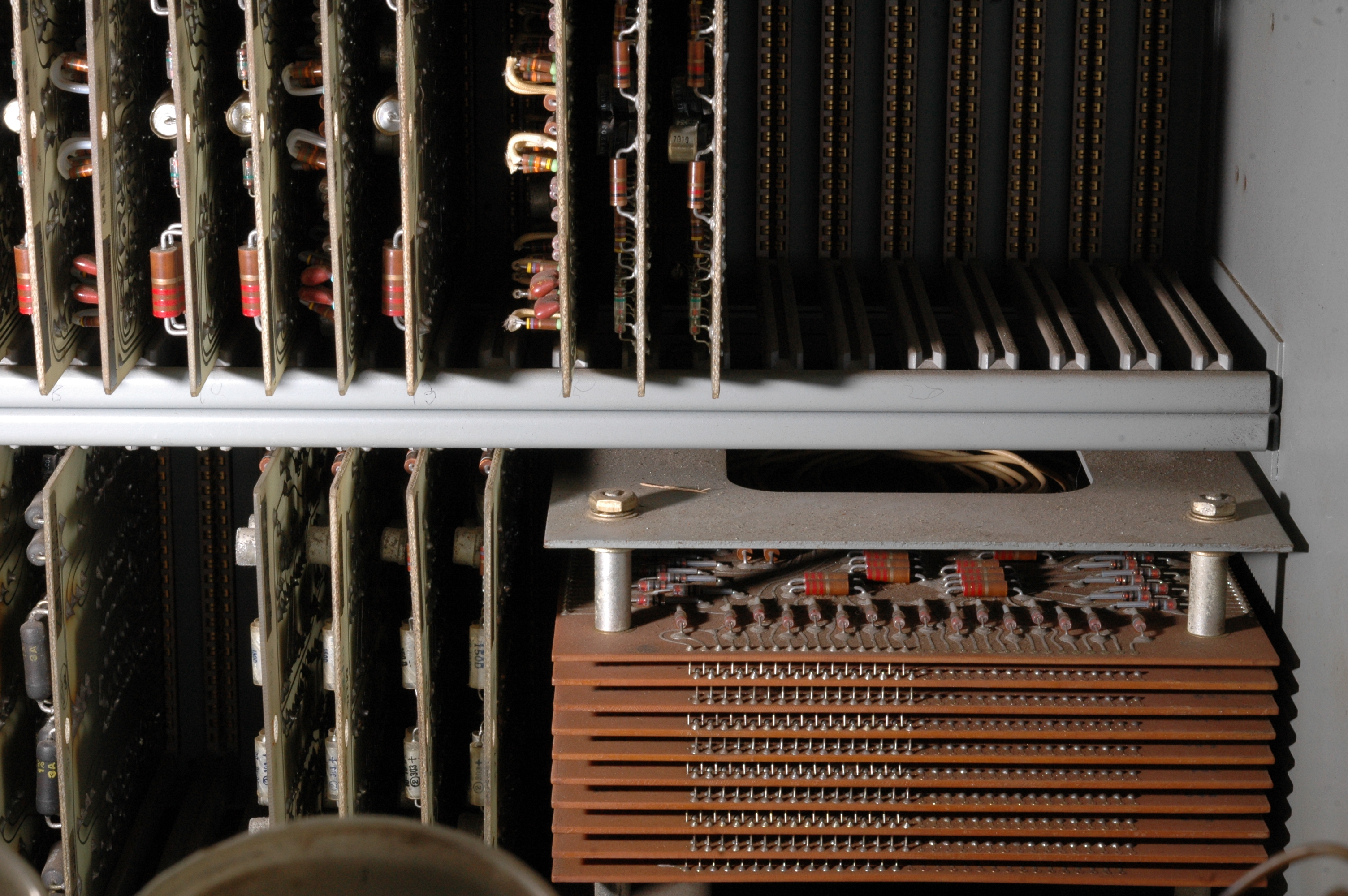
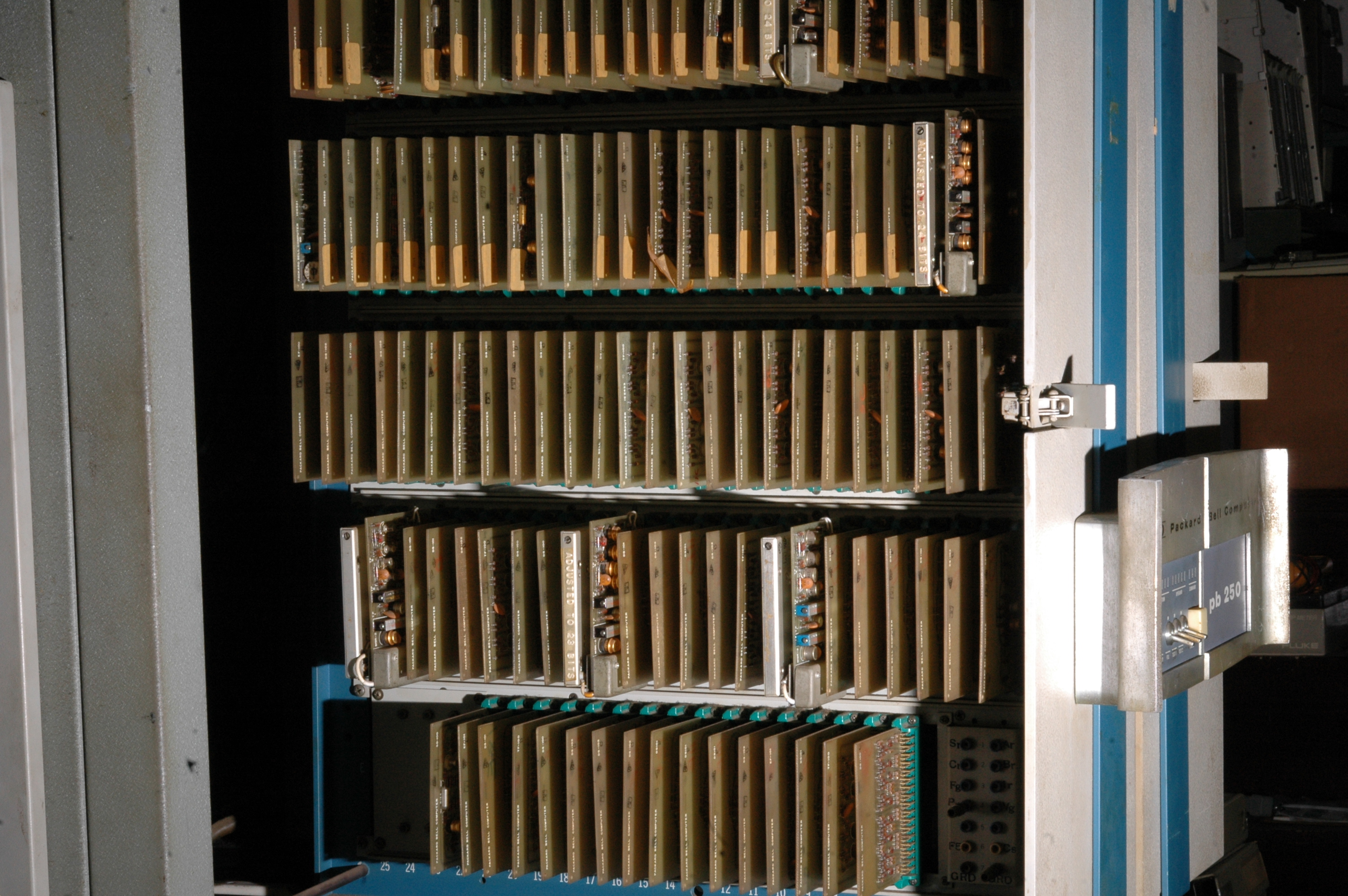
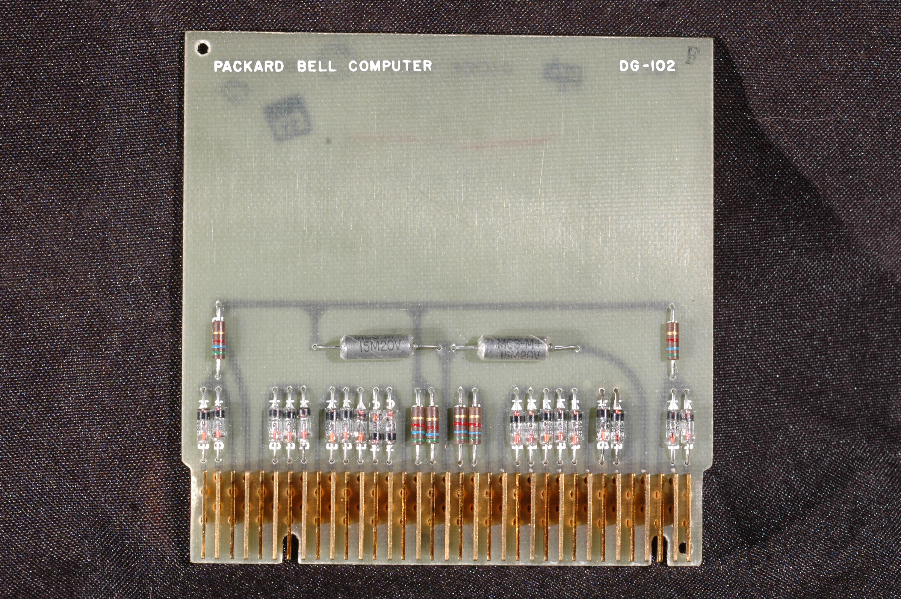
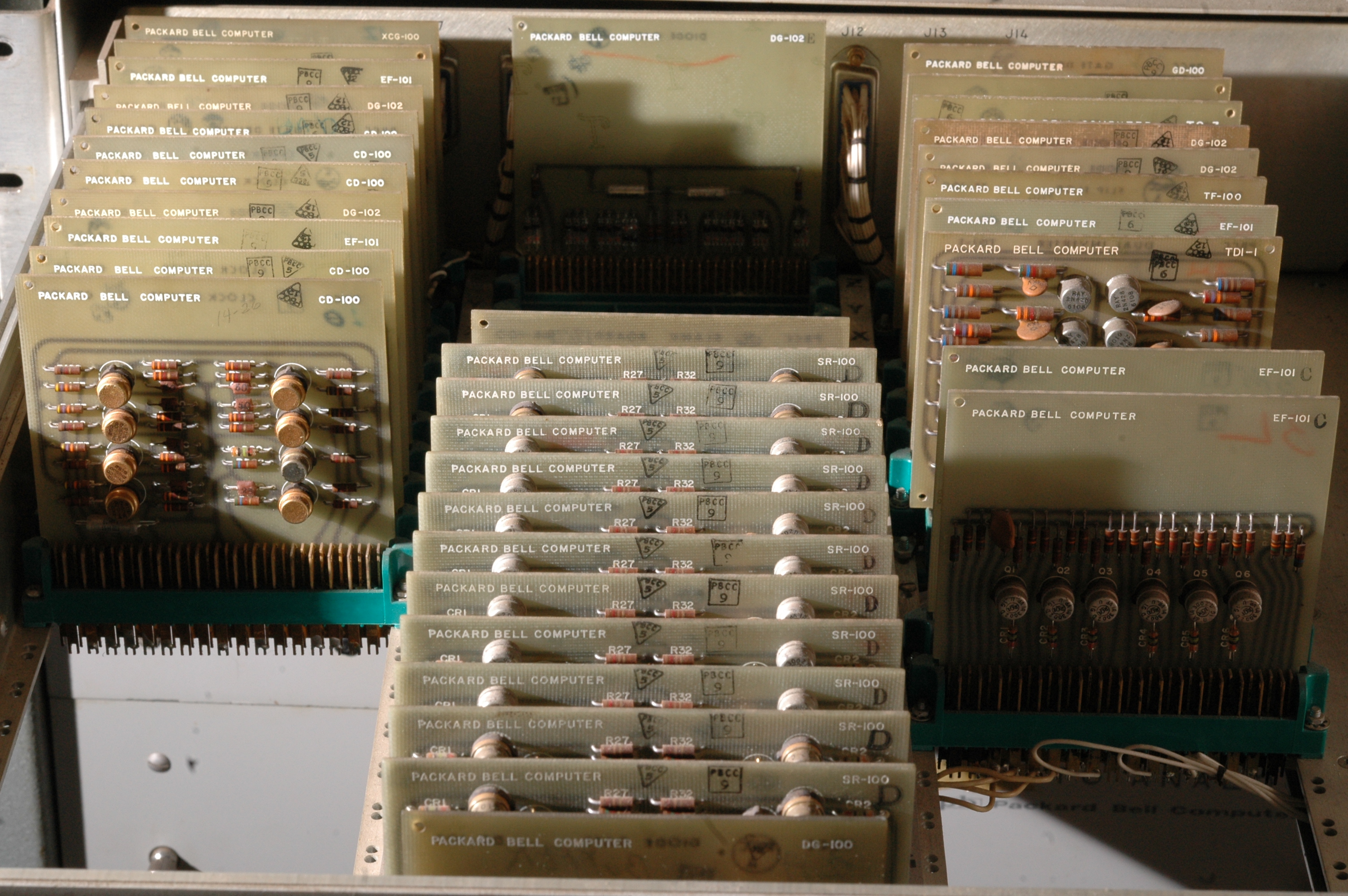
The computer is composed of a large number of small boards, each of which performs a simple generic operation: AND gates, flip-flops, etc.
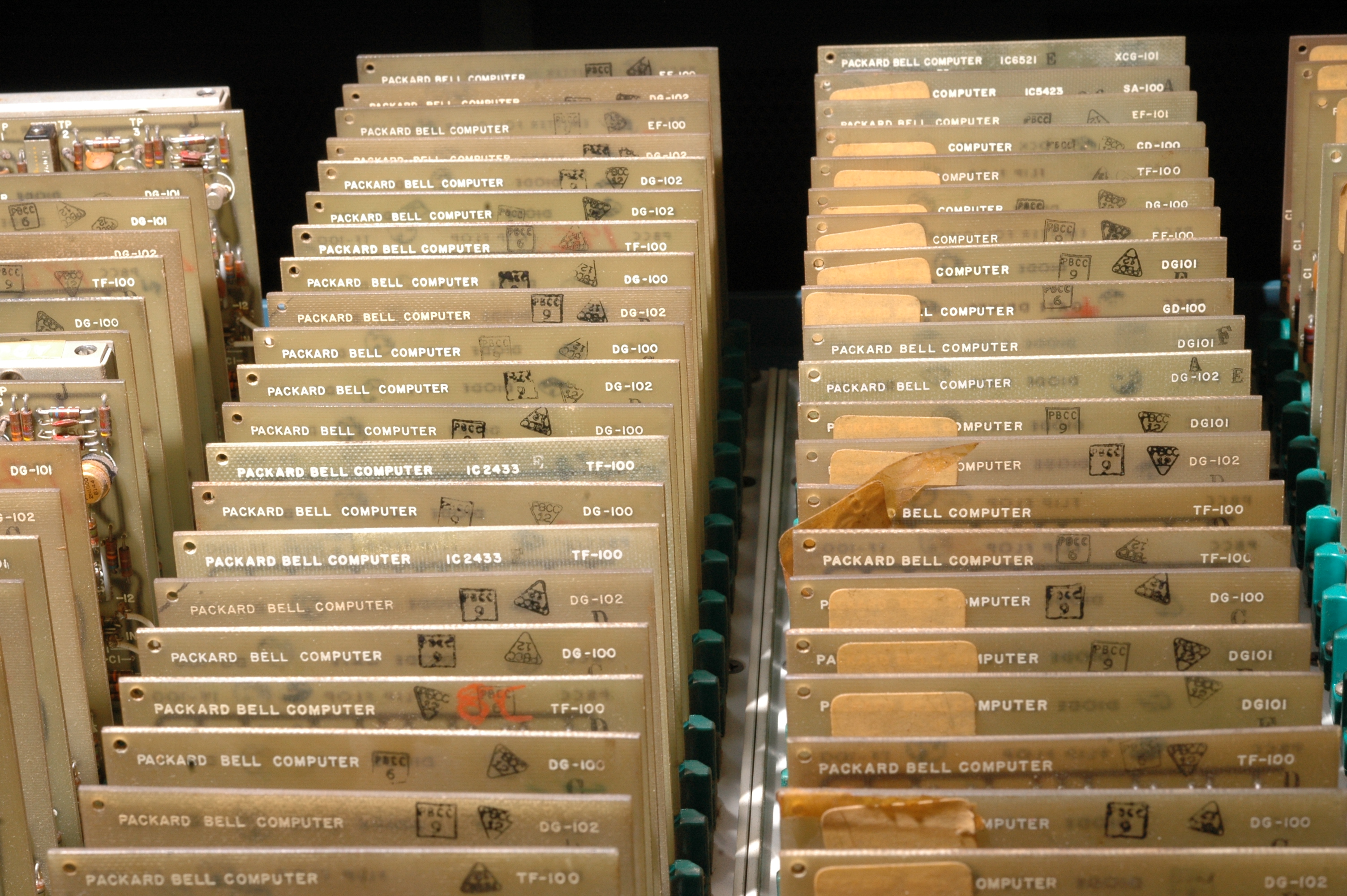
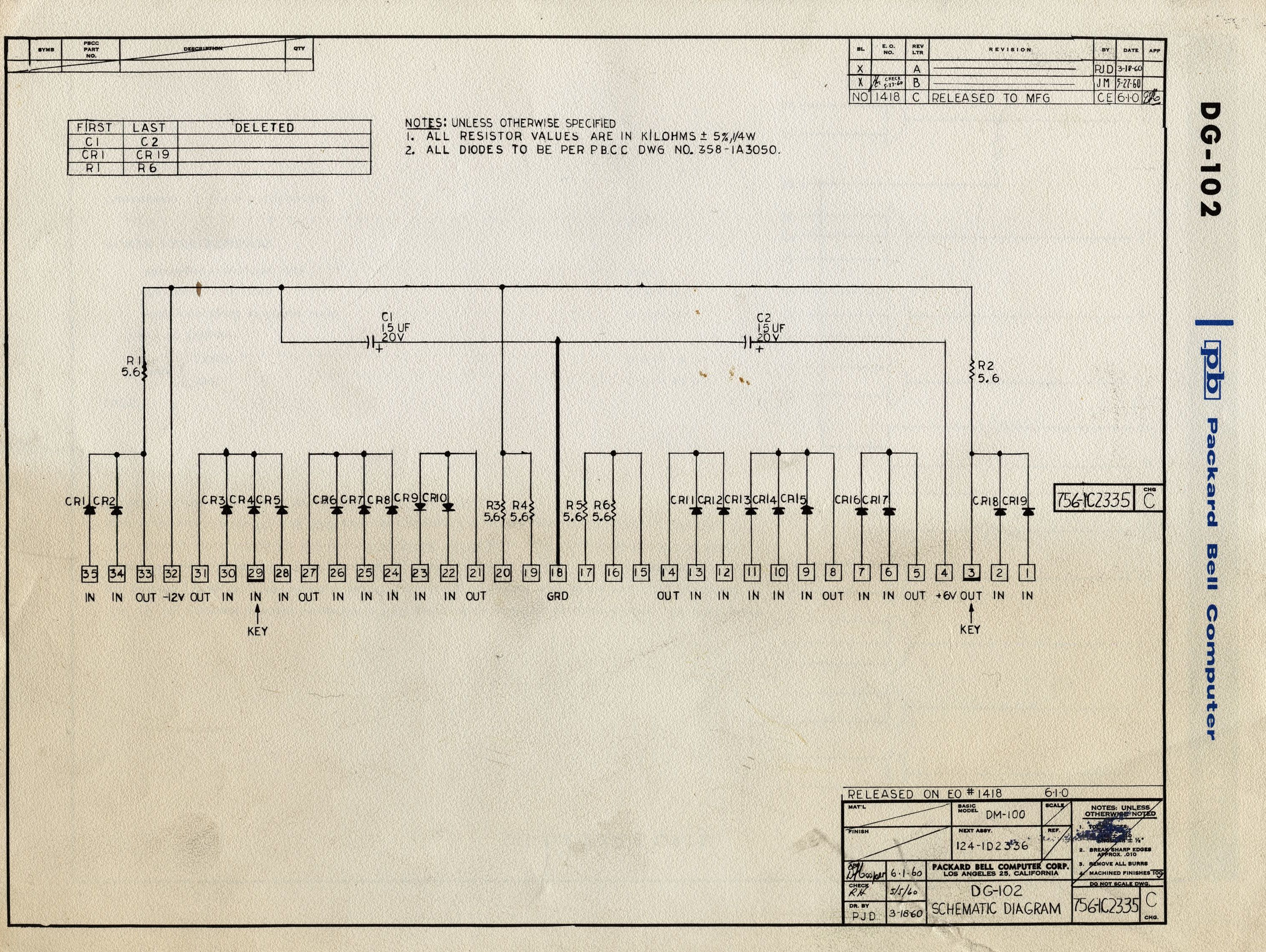
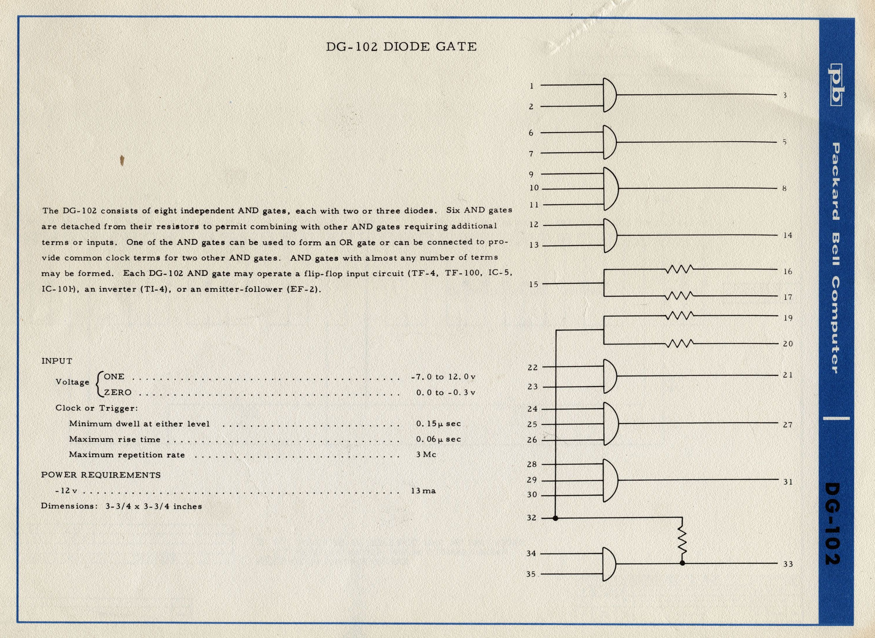
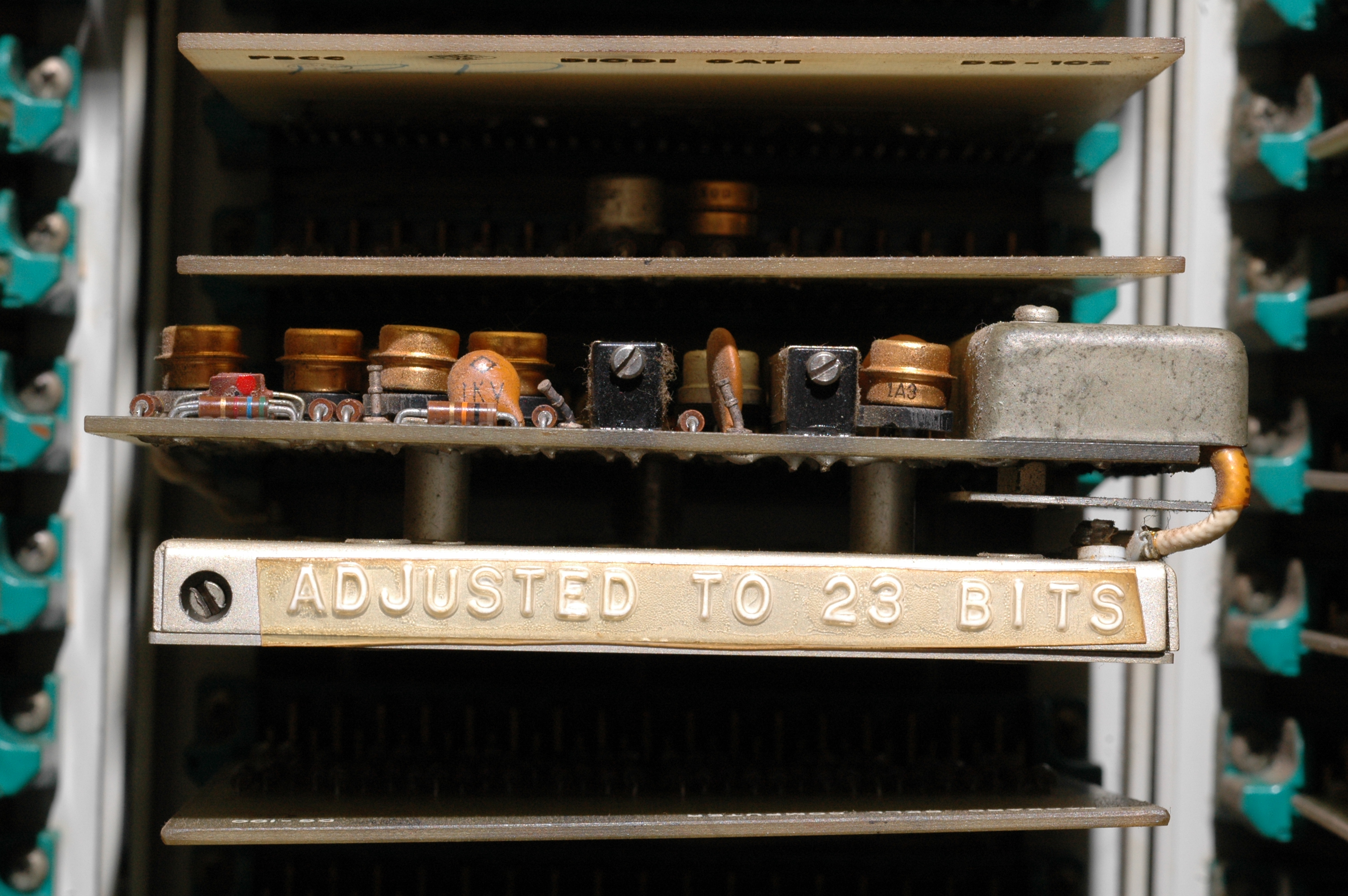
An example of these simple logic boards is the DG-102 diode gate board, which provides eight AND gates.
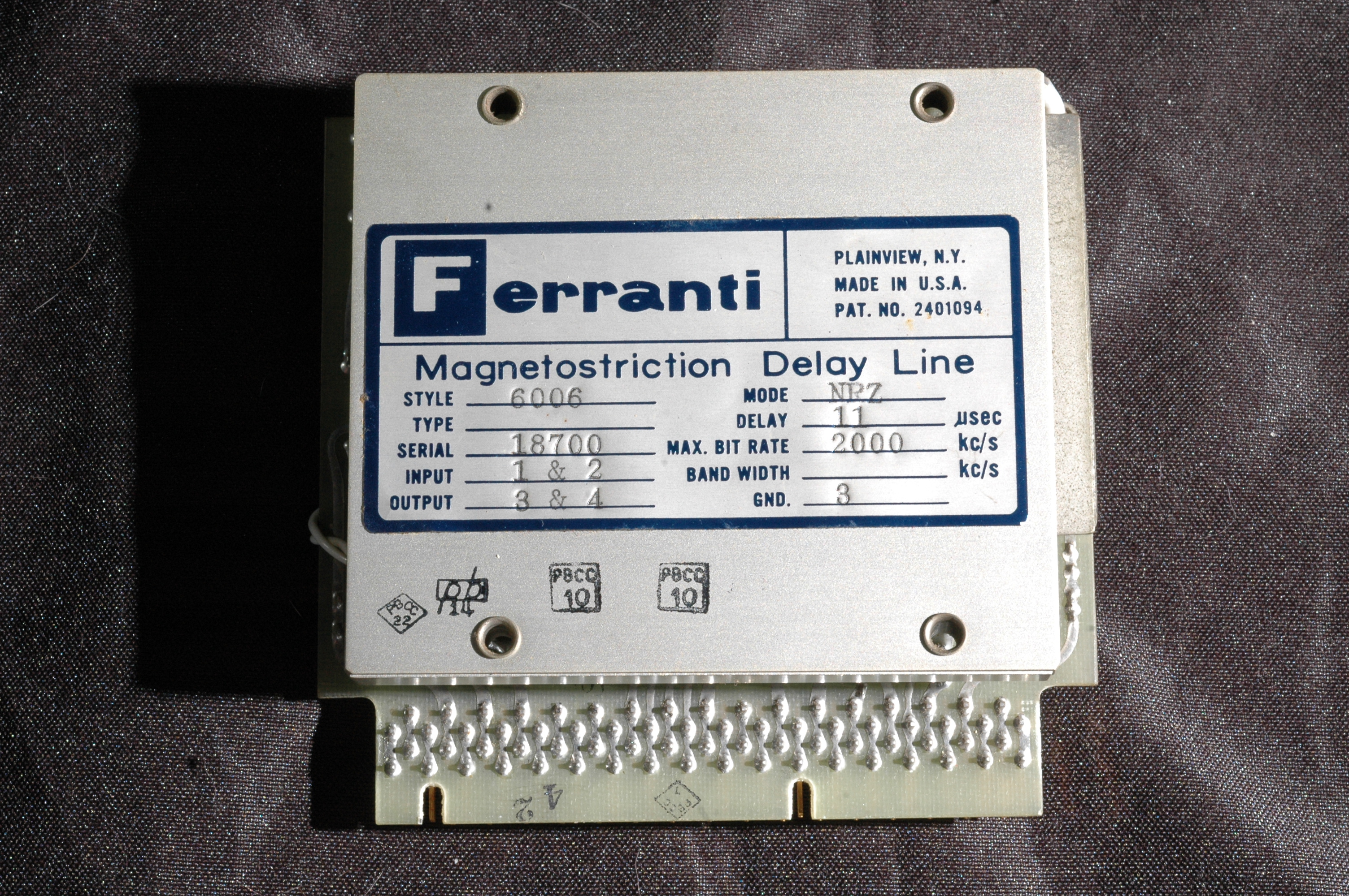
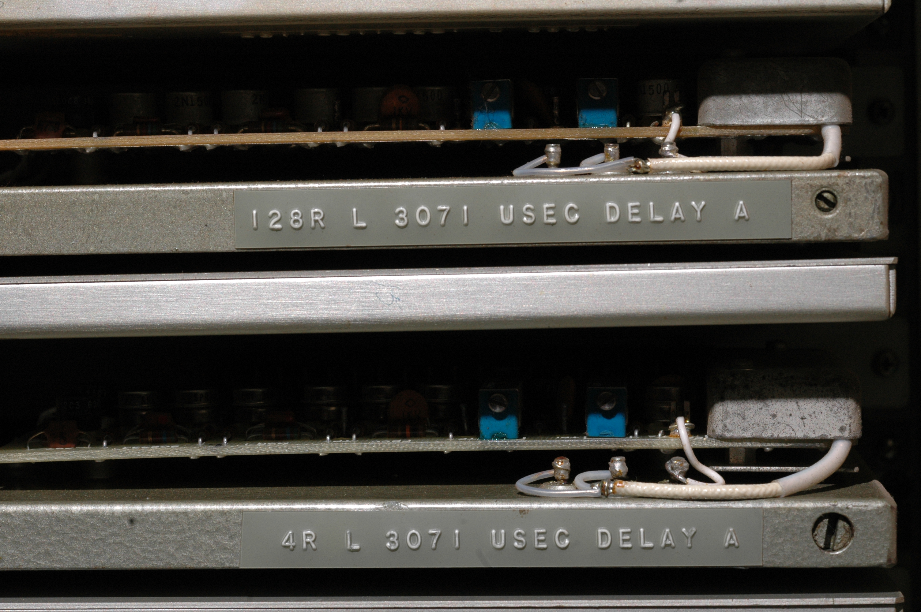
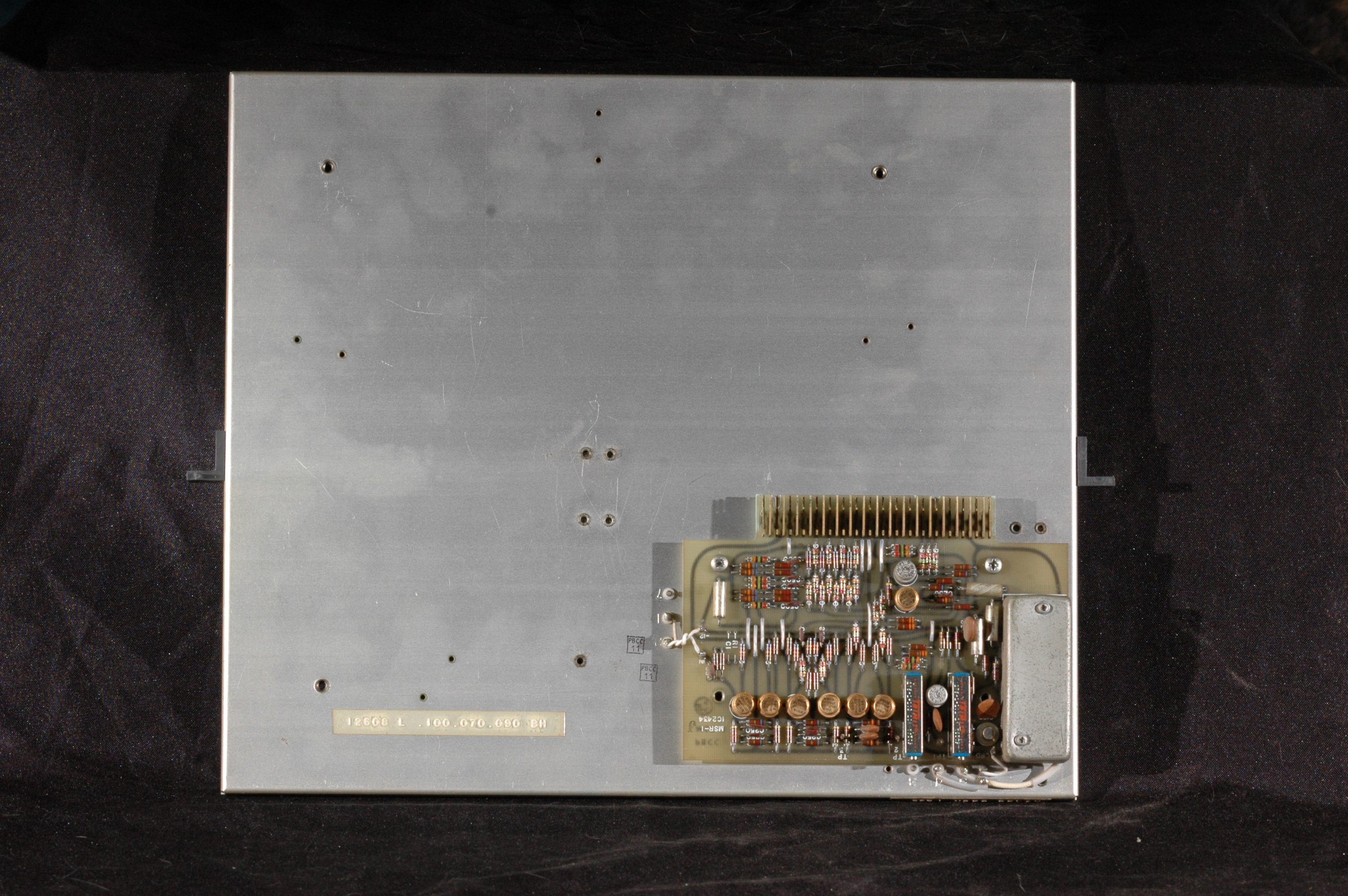
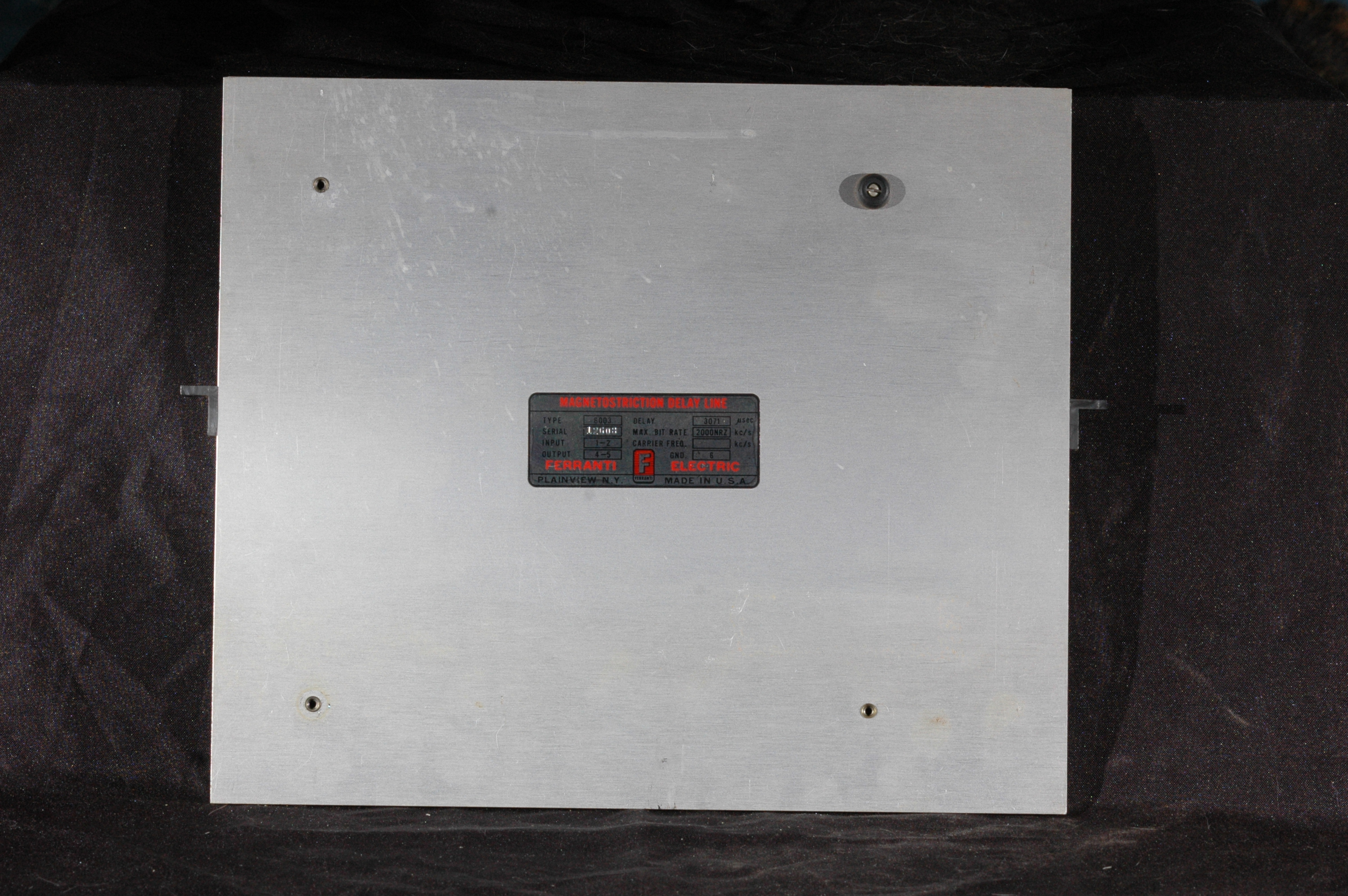
The PB-250's memory consists of magnetostrictive acoustic delay lines. That is: a long piece of wire down which a mechanical pulse is sent. Each pulse is detected when it reaches the end of the wire, and retransmitted from the beginning. The data in memory consists of the pulses in mid-flight traveling down the wire.
Since a given word is only accessable when it comes around to the head of the delay line, there is a 256-fold difference in memory access time depending on where the word is currently in the delay line. The location of data and instructions in memory thus becomes very important (and complex), in order to run the computer efficiently. To help with this, each instruction includes a flag which determines if the next instruction will be at the next sequential location, or at the address that is available at the time the next instruction begins. (ie: packed sequentially in memory, or spaced out for optimal timing.) Arranging data efficiently throughout the address space is left to the programmer.
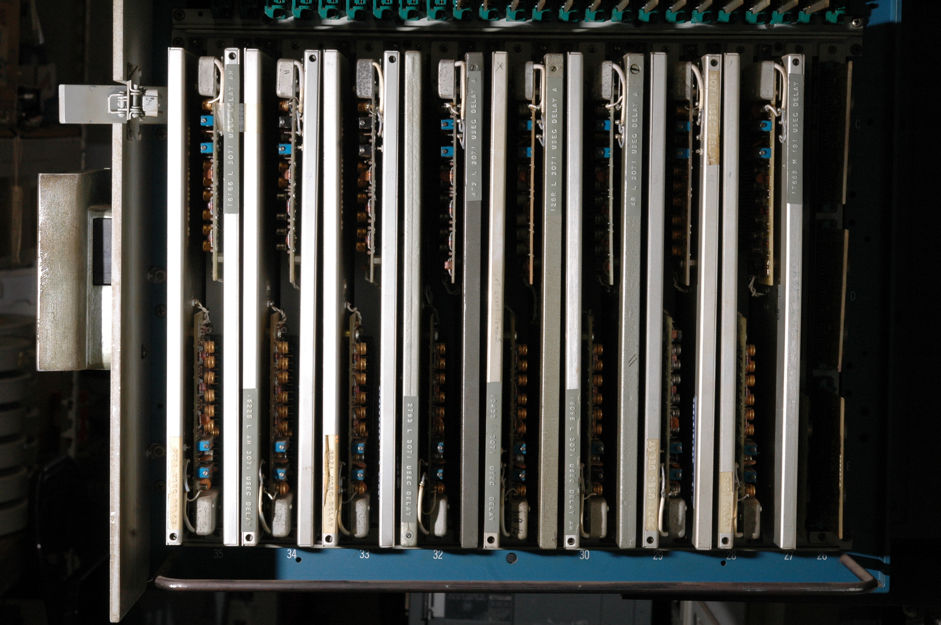
There are five short (single 22-bit word) delay lines, which store the three arithmetic registers (A, B, and C), the instruction register, and the sector counter (the current address in the long delay lines). Main memory (on this particular PB-250) consists of one "fast access" line (16 22-bit words) and fifteen "long" lines (256 22-bit words). Other memory configurations were available.
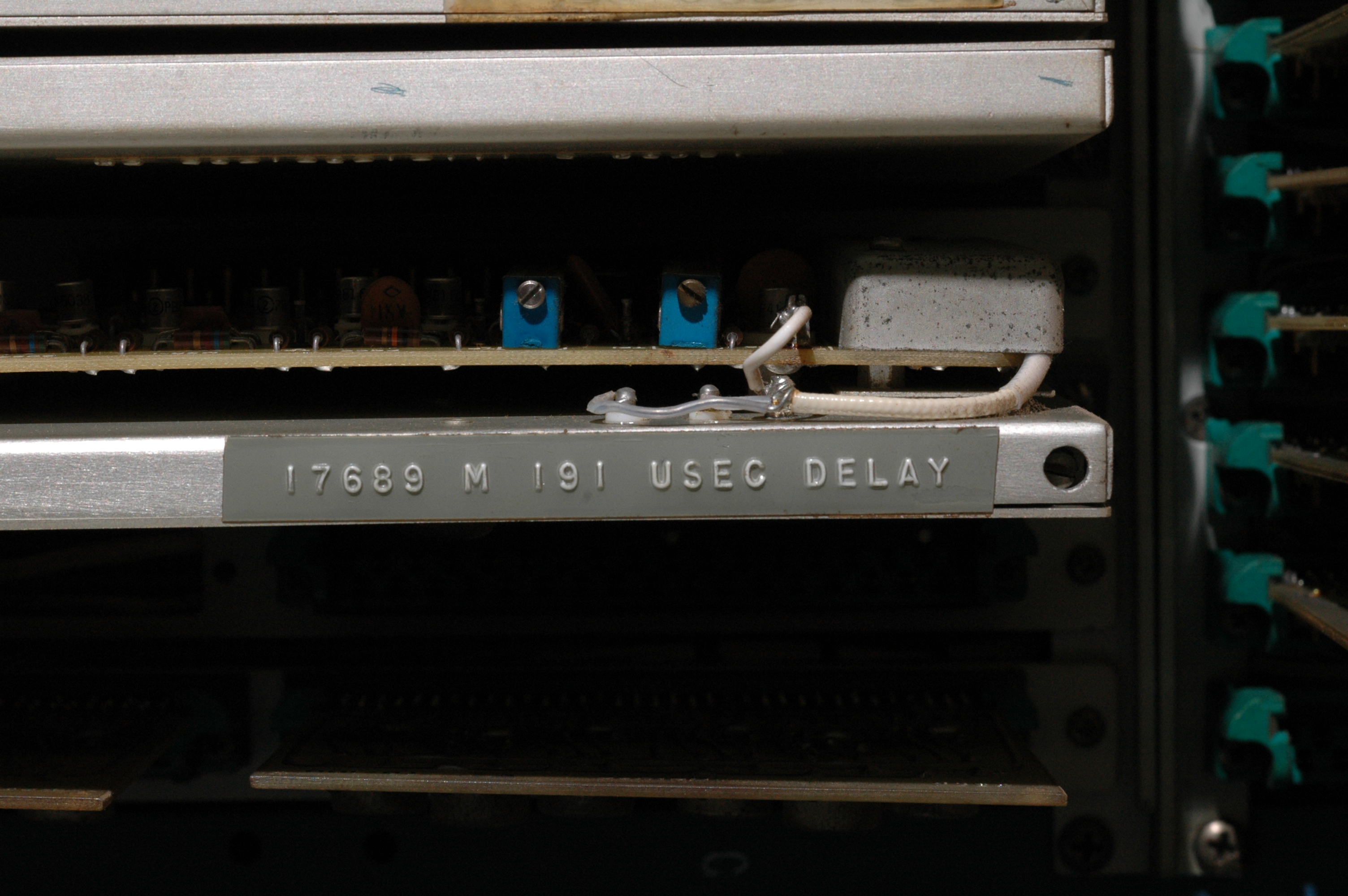
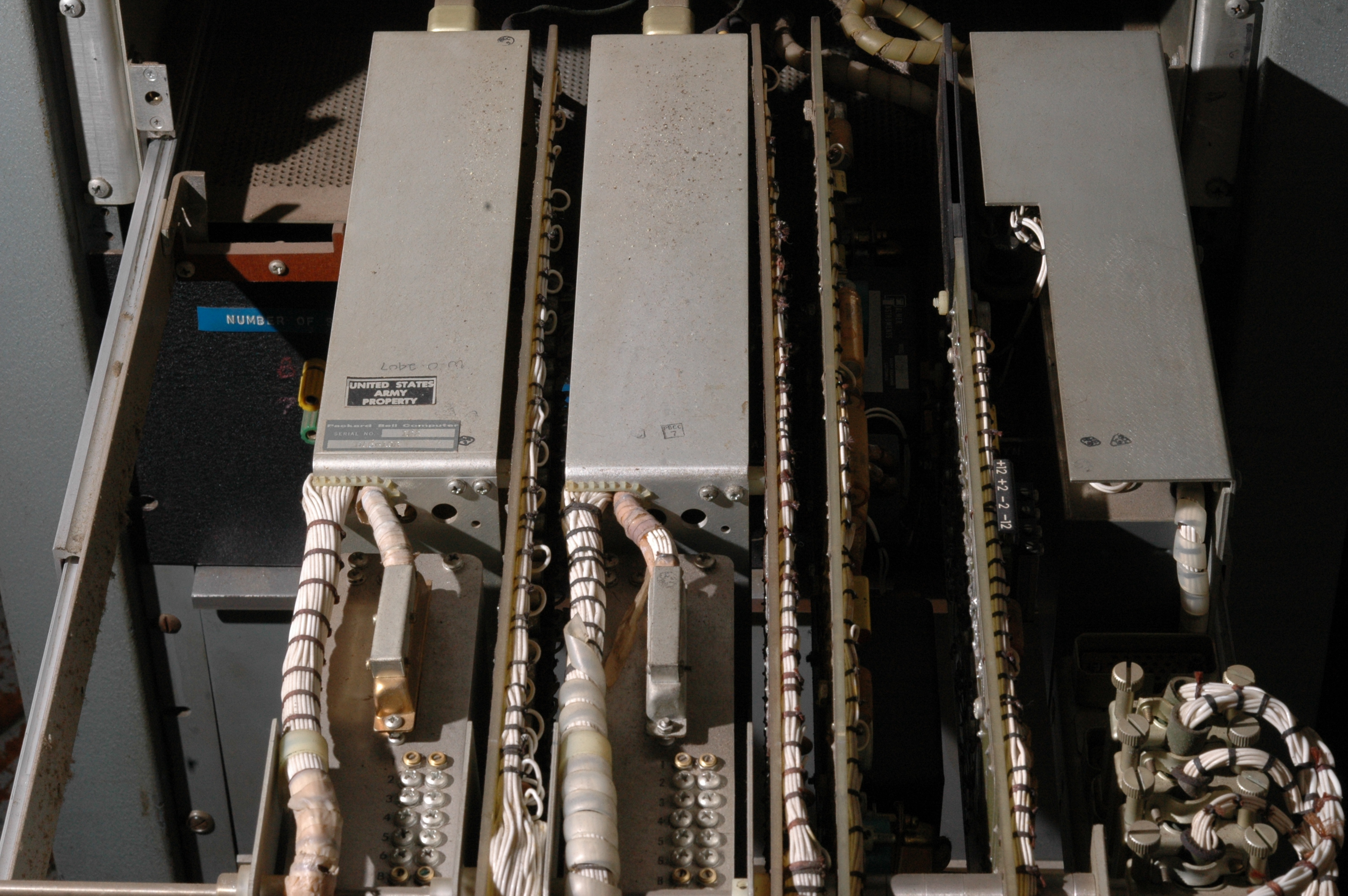
The sealed modules are the delay lines. The small ones for registers, the large ones for main memory. (Most of the long lines are tuned to 3071 microseconds, but line 0 (the fast access line) is tuned to 191 microseconds.)
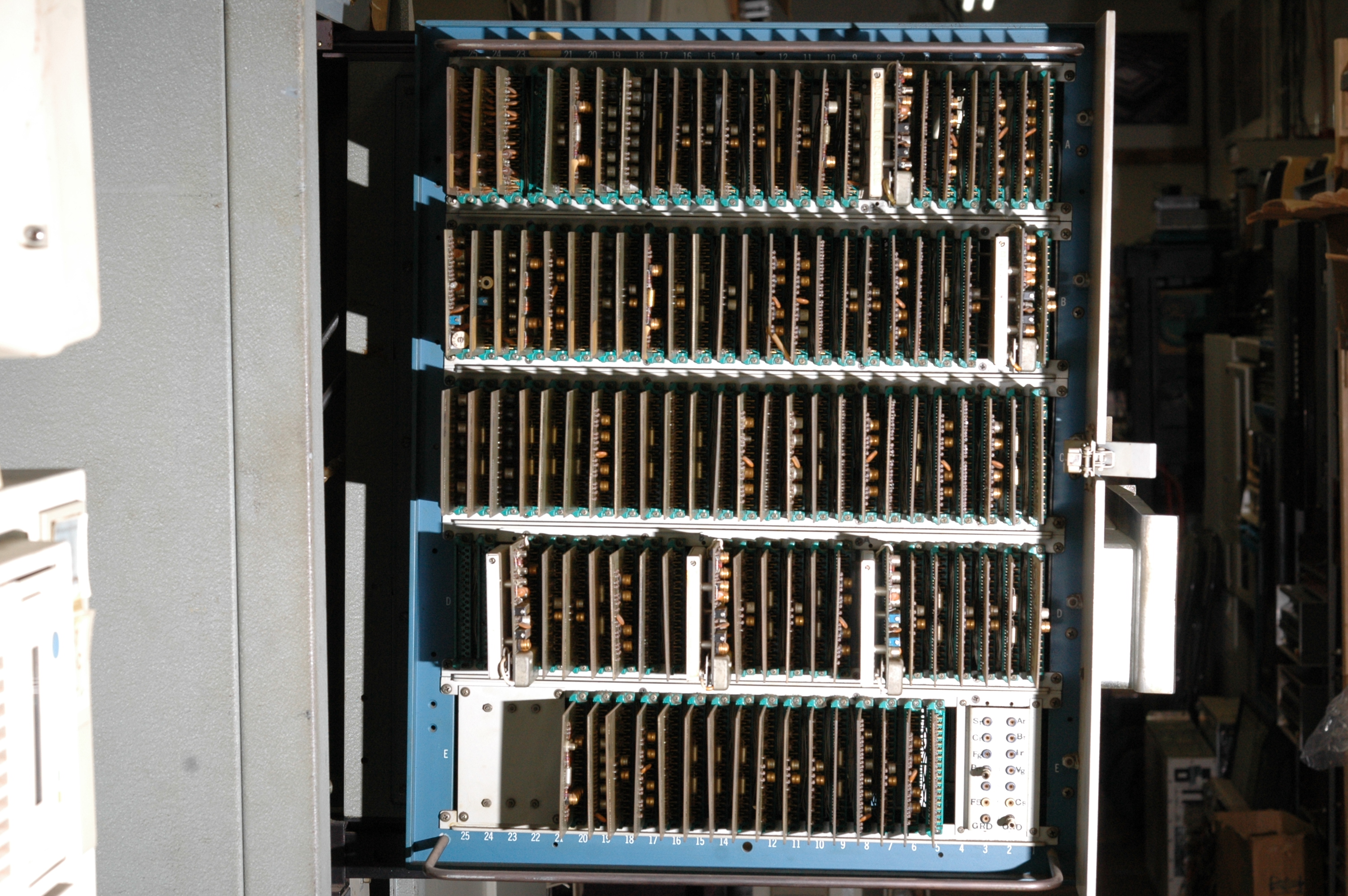

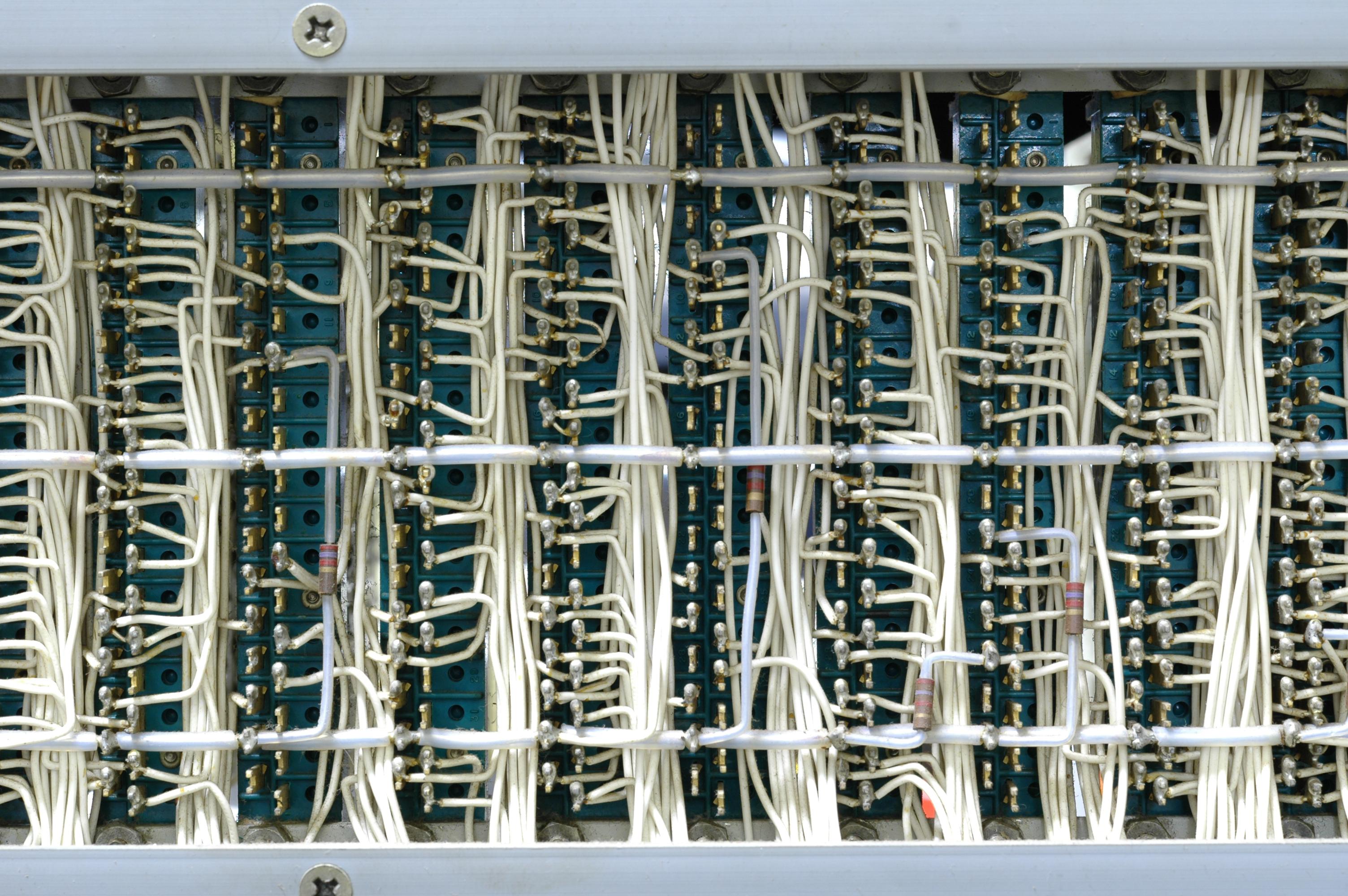
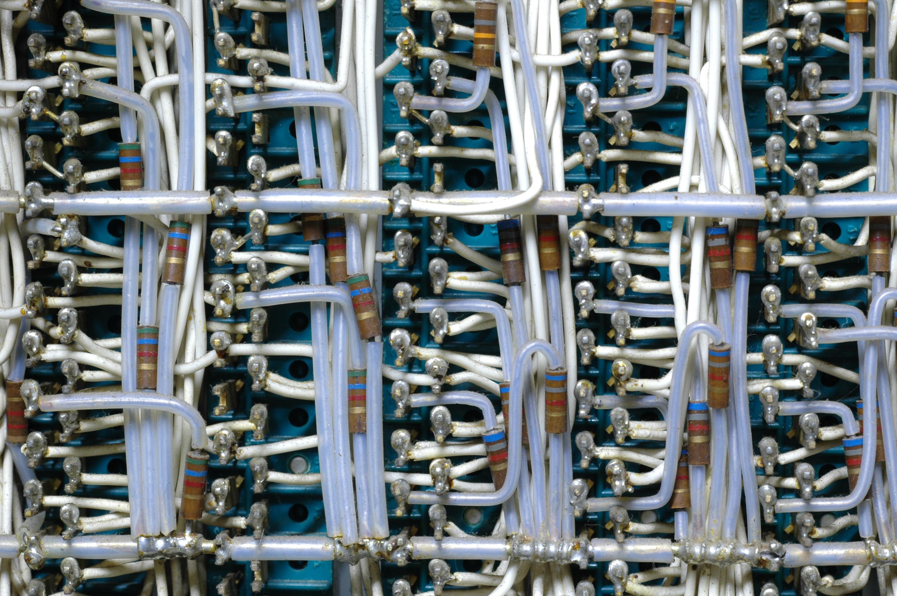
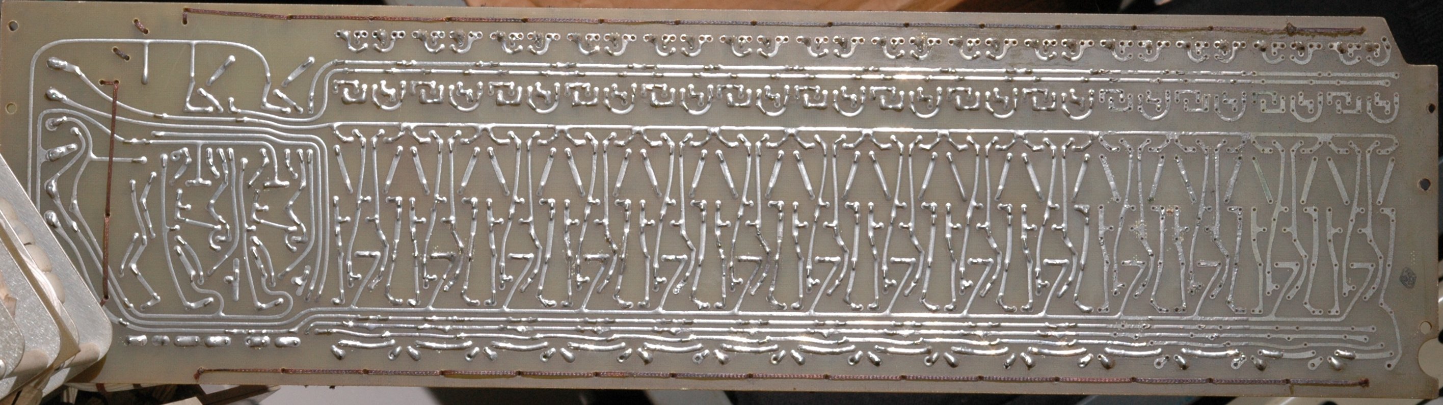
The backplane is soldered, rather than wire-wrapped.
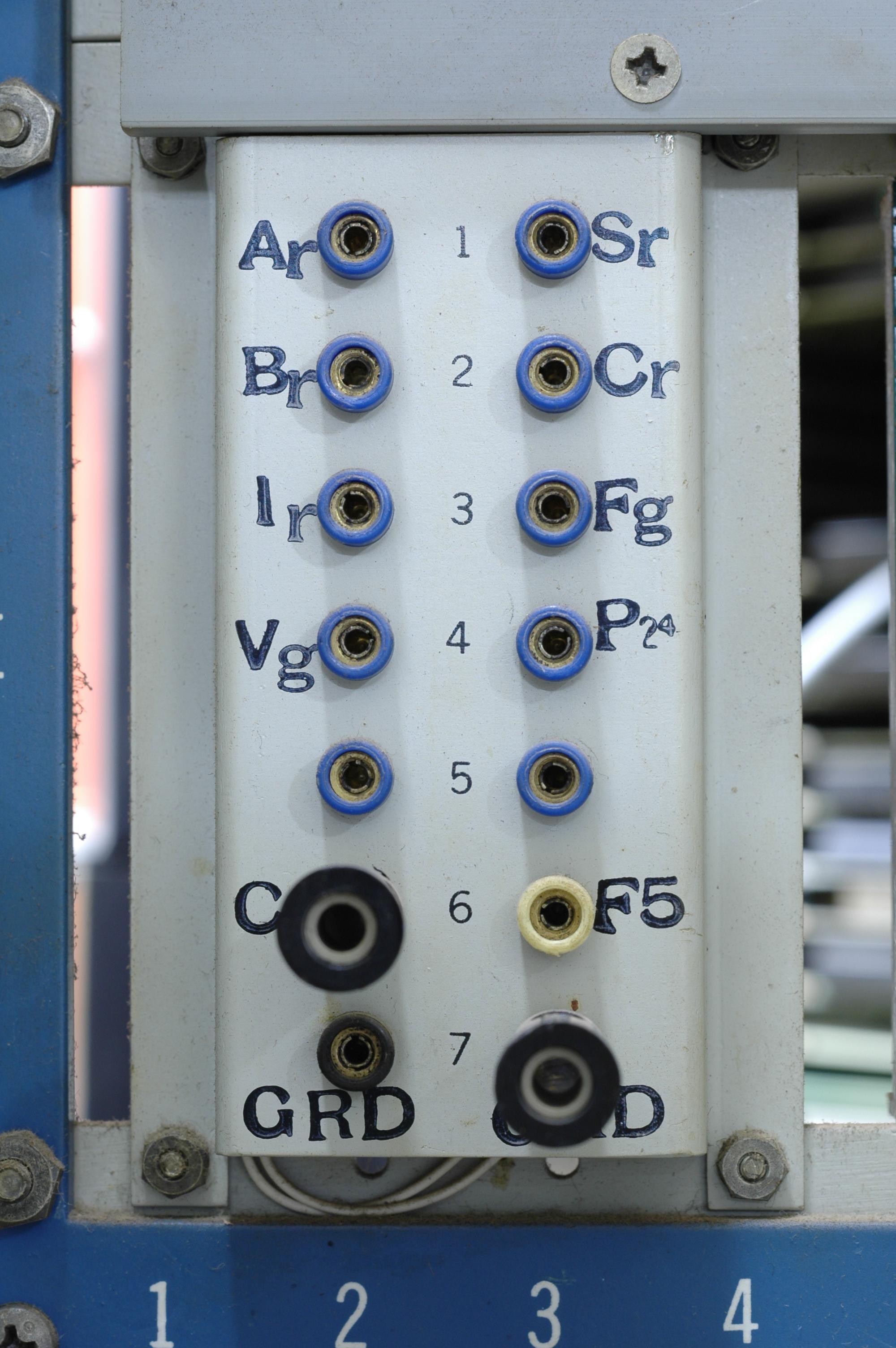
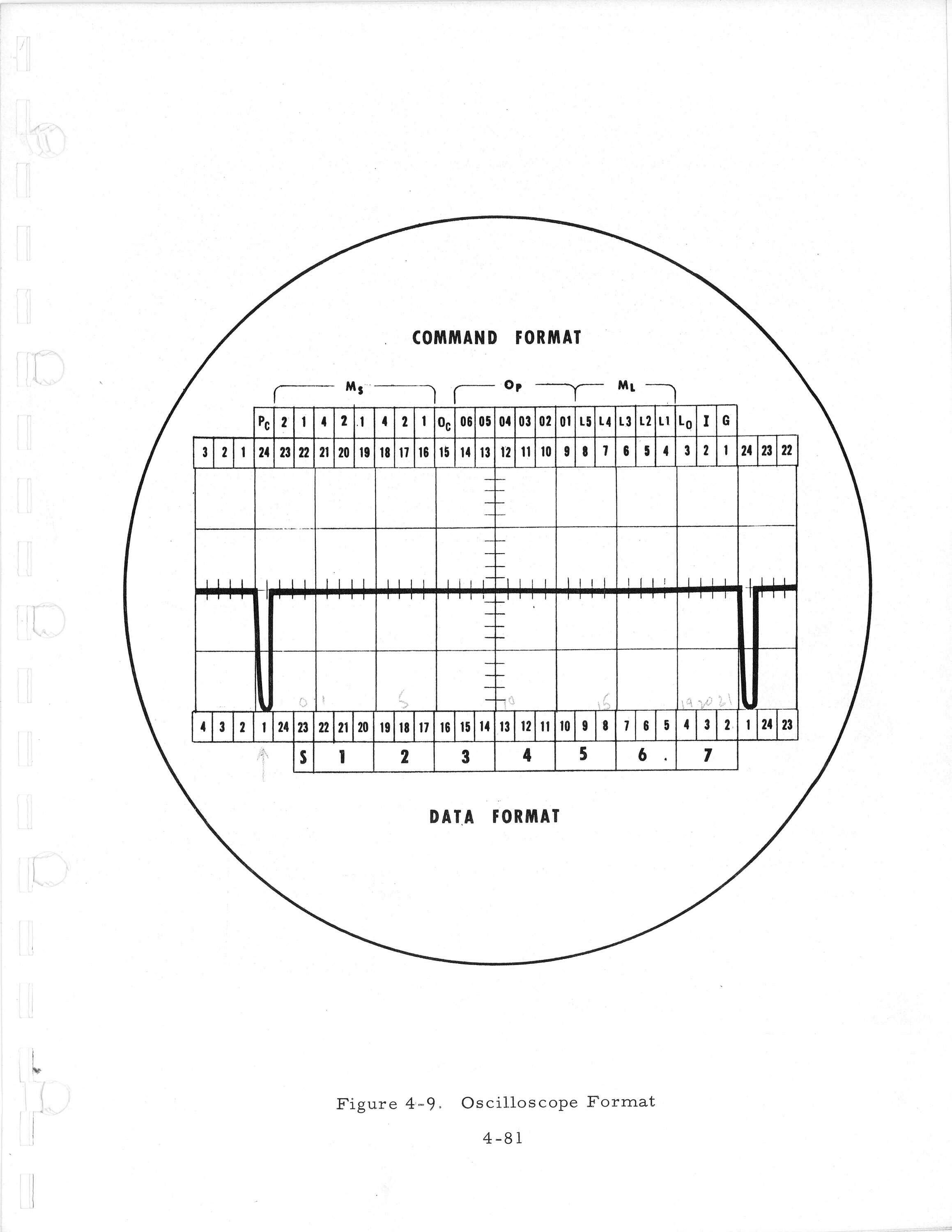
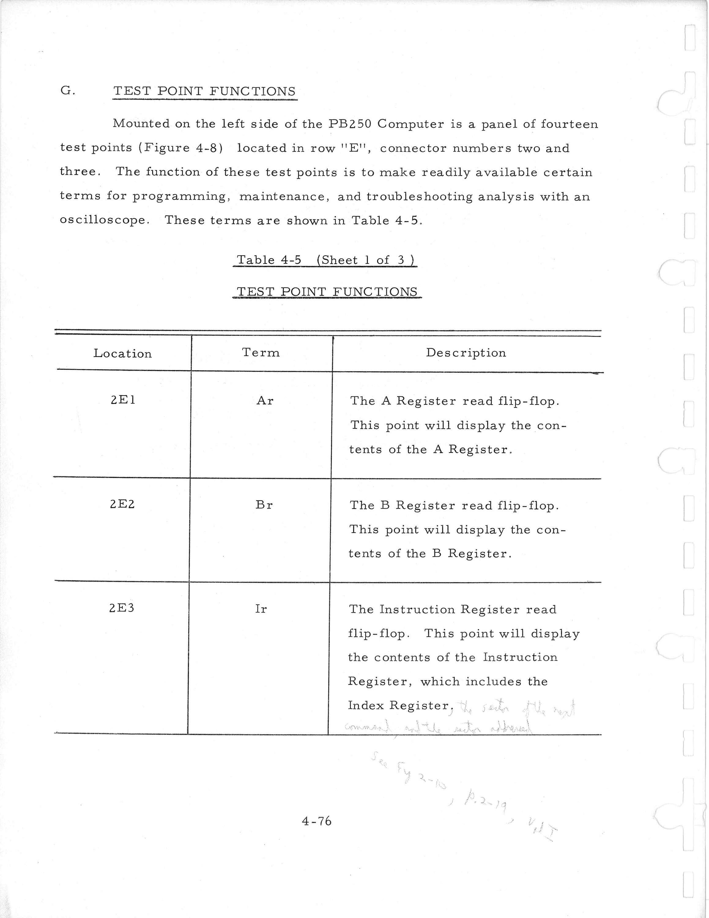
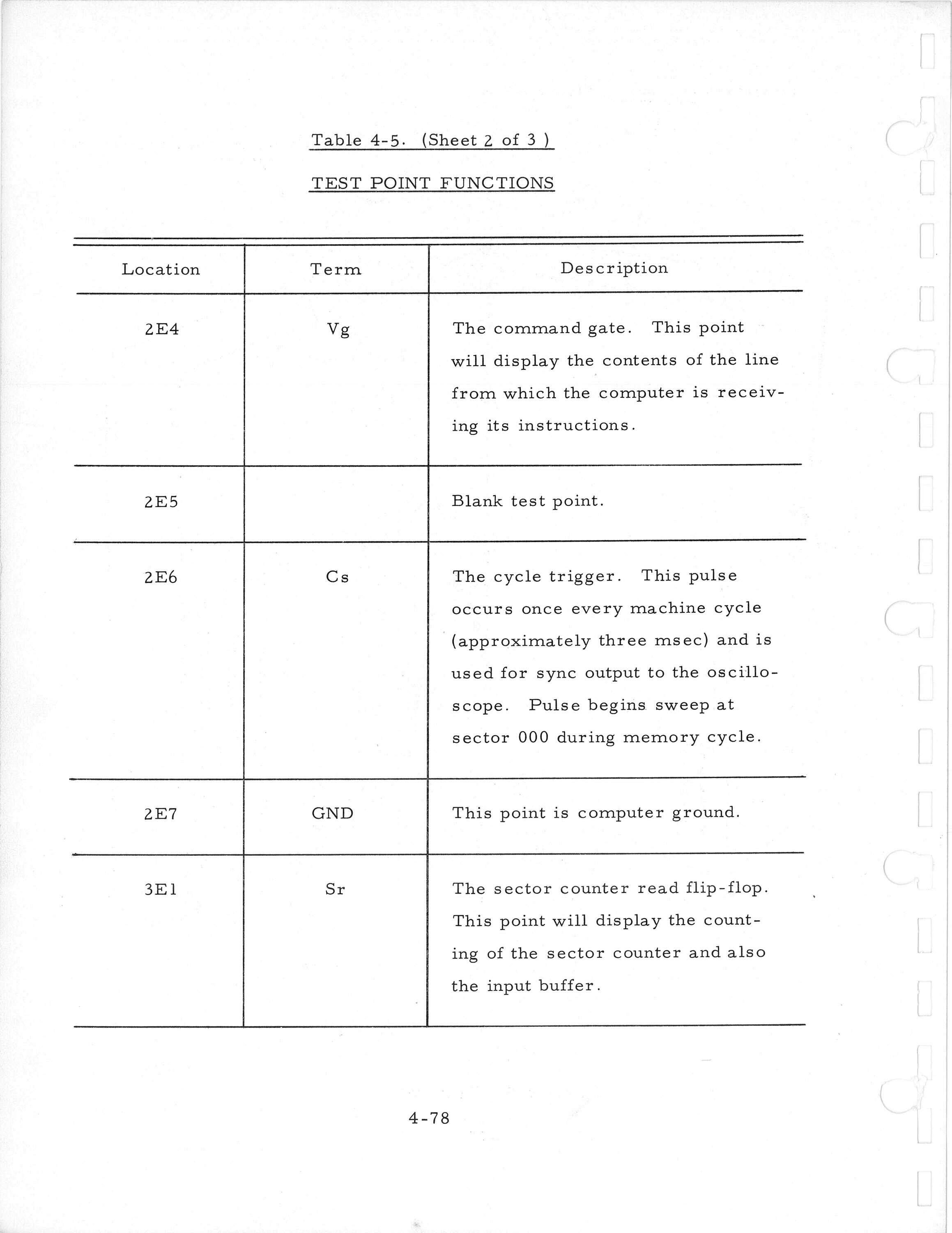
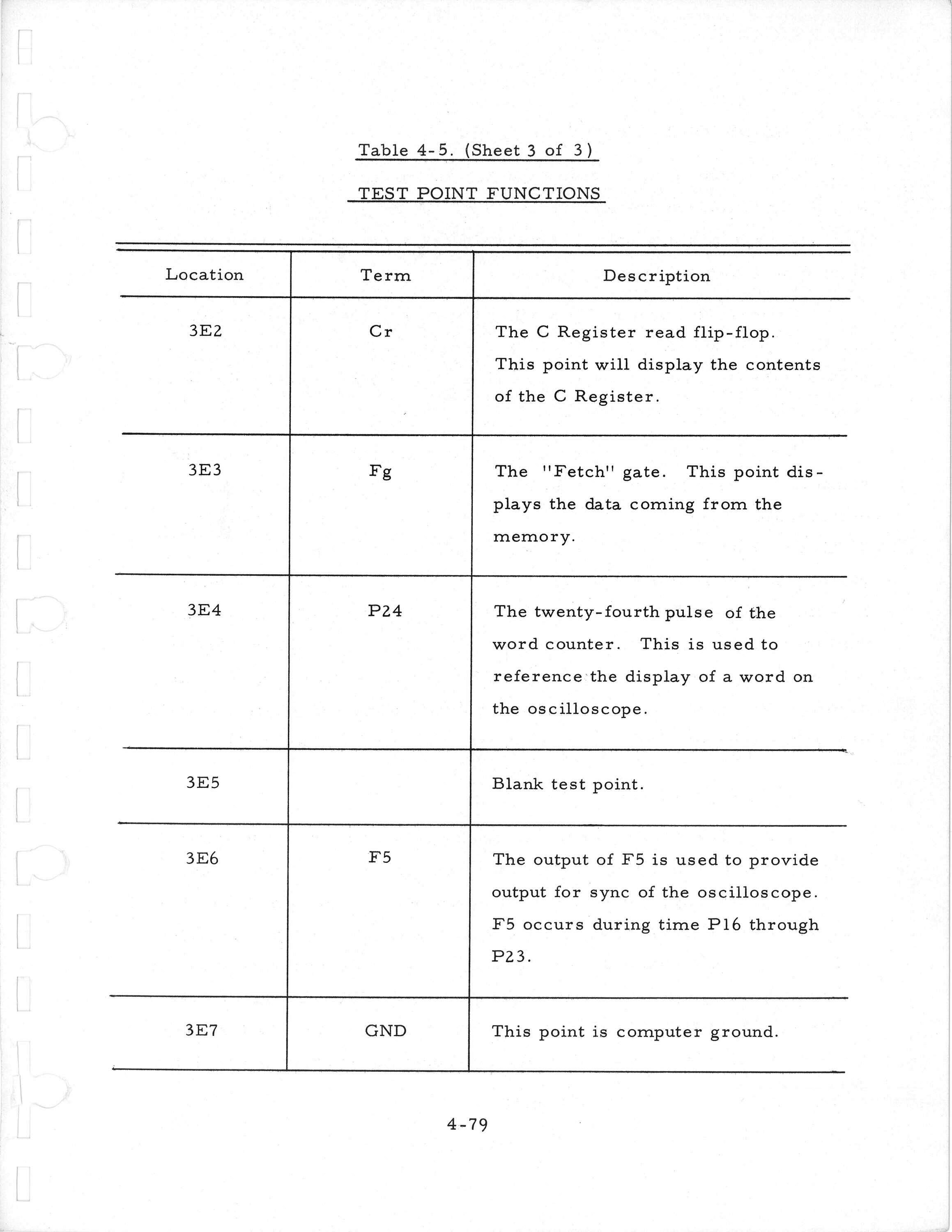
As the PB-250 lacks a complete front panel, it includes test points to attach an oscilloscope to view internal data registers.
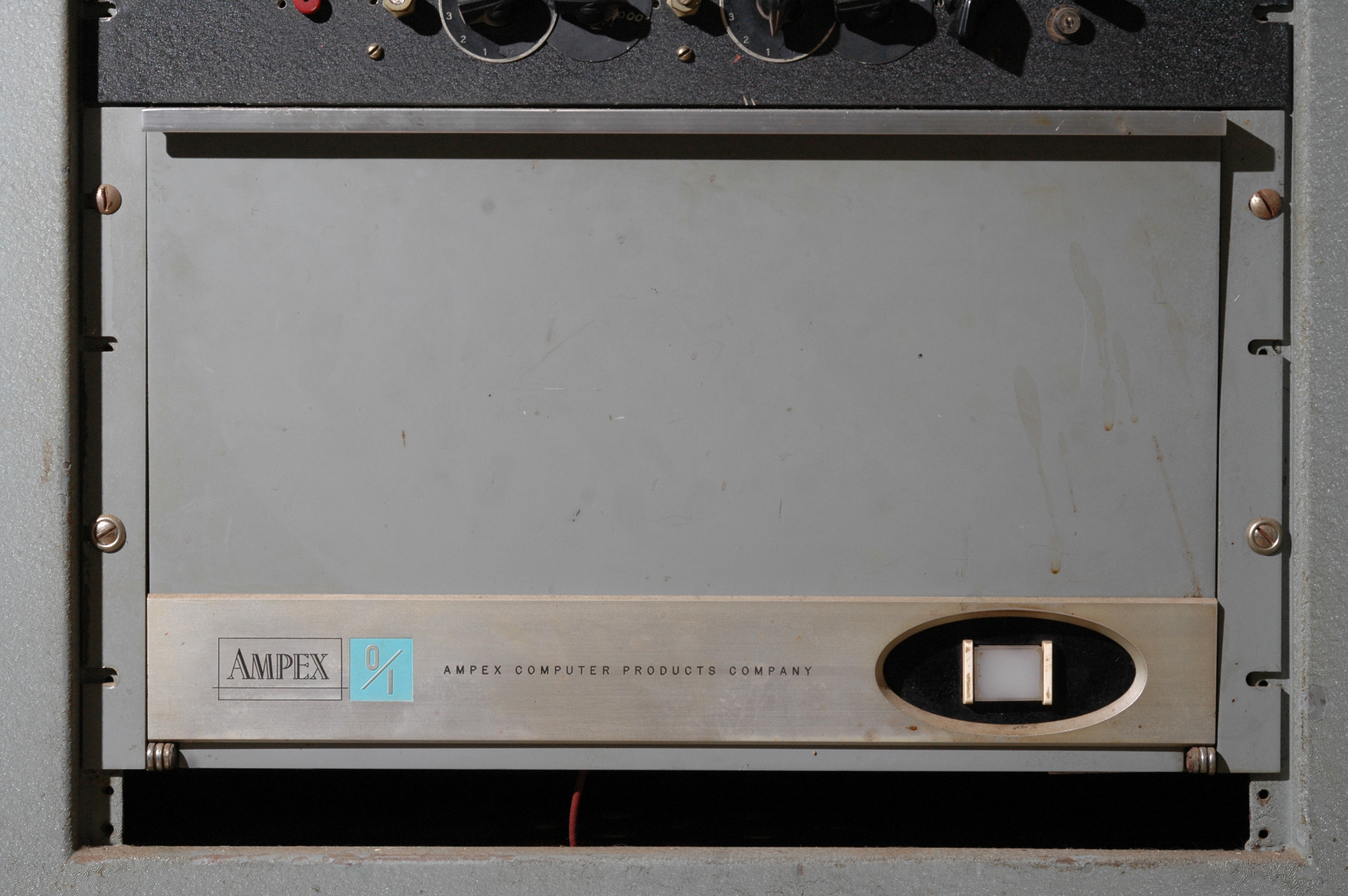
This system includes the main computer, plus extra hardware for interfacing to external data sources: a high speed buffer, mutiverter, D-to-A, and external core memory.
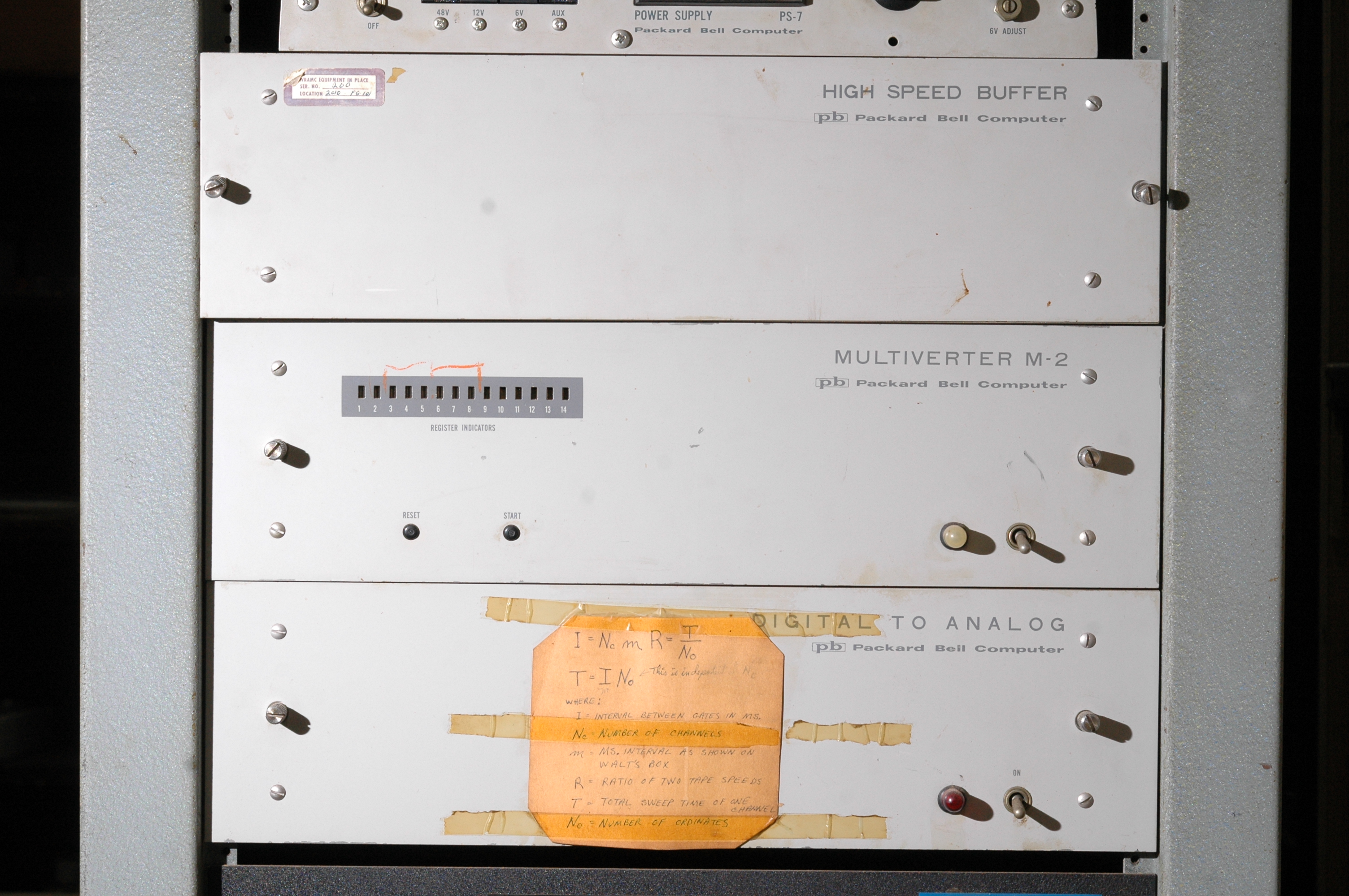
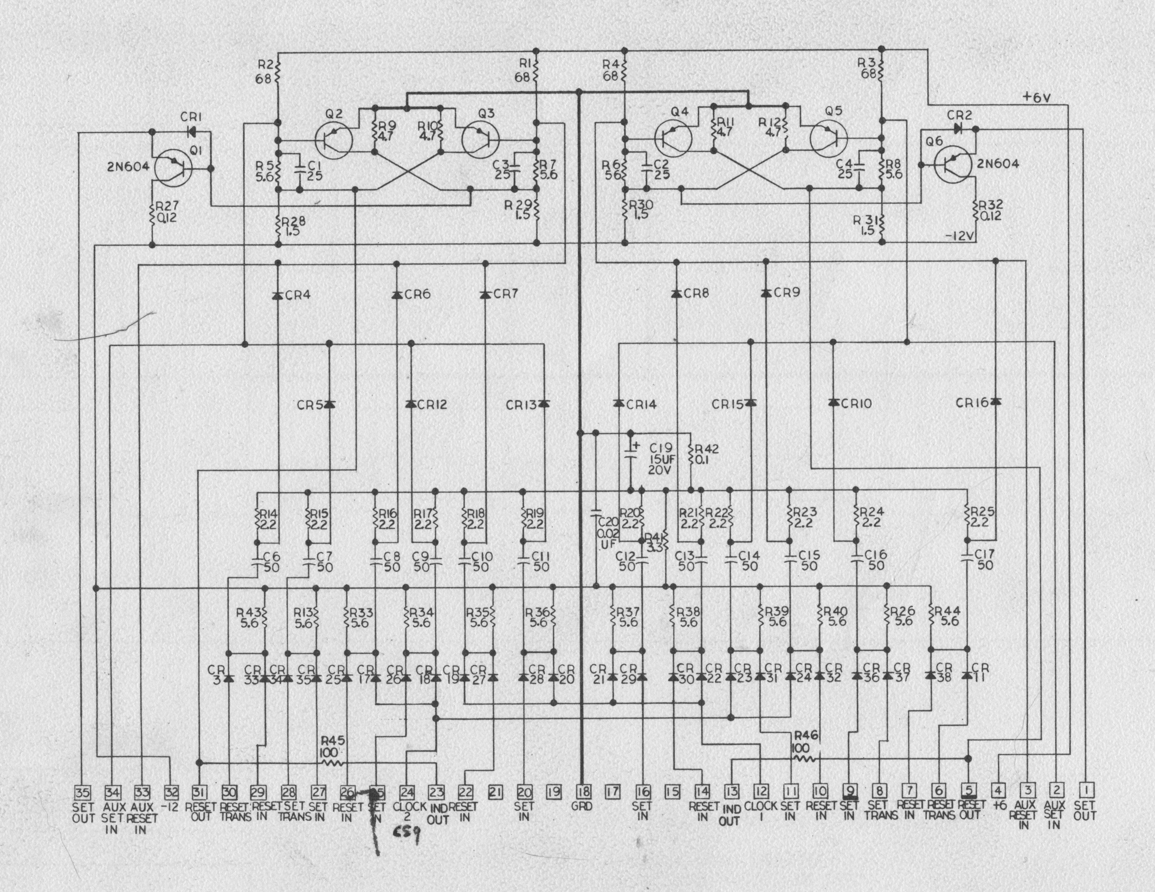
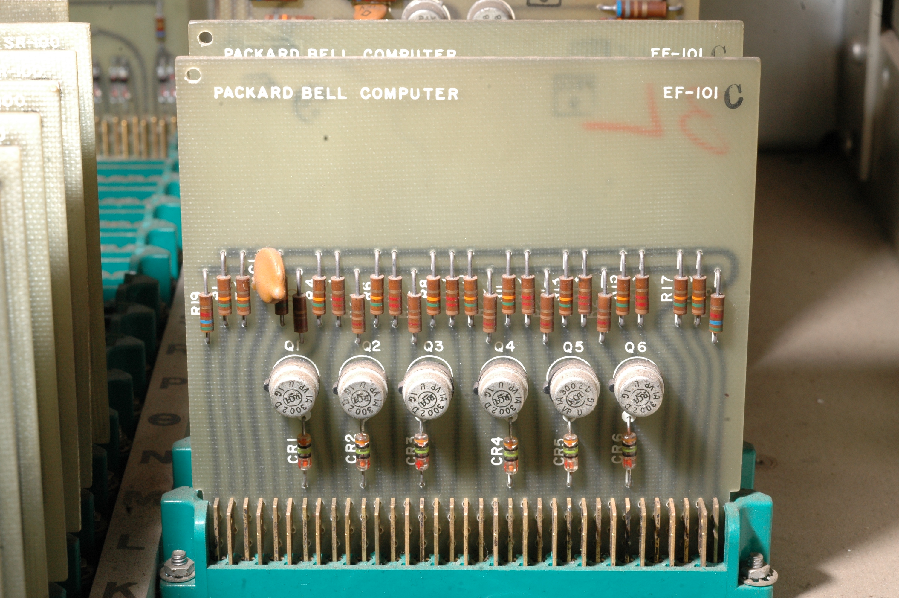
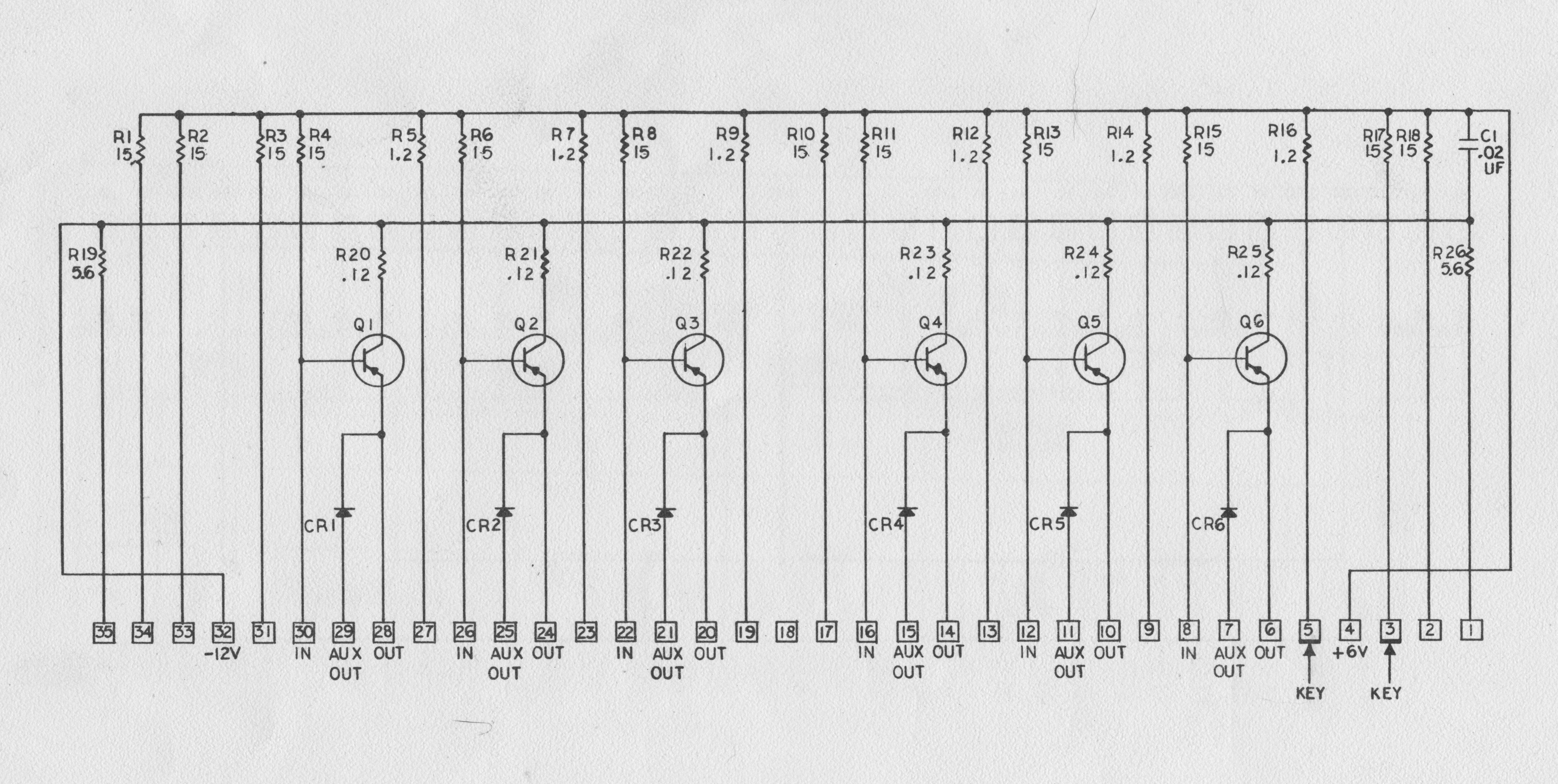
The High Speed Buffer stores 22 bits to allow transfer between the PB-250 and high-speed asynchronous devices. Storage is provided by shift register cards. Each SR100 board stores two bits. These are schematics for the SR100 shift register board and the EF101 emitter-follower board.
The D-to-A unit allows the computer to generate analog signals to interface with real world processes.
The external core memory allows a burst of data to be stored until the CPU has time to process it.